Two-post lift safety locks: why mechanical backups work
A two-post lift can raise 9,000 to 11,000 lb of vehicle mass in roughly 60 to 66 seconds. Hydraulic pressure performs the lifting. It is not the only system permitted to hold the load.
Aldous Moorland·Updated: August 17, 2026·15 min read
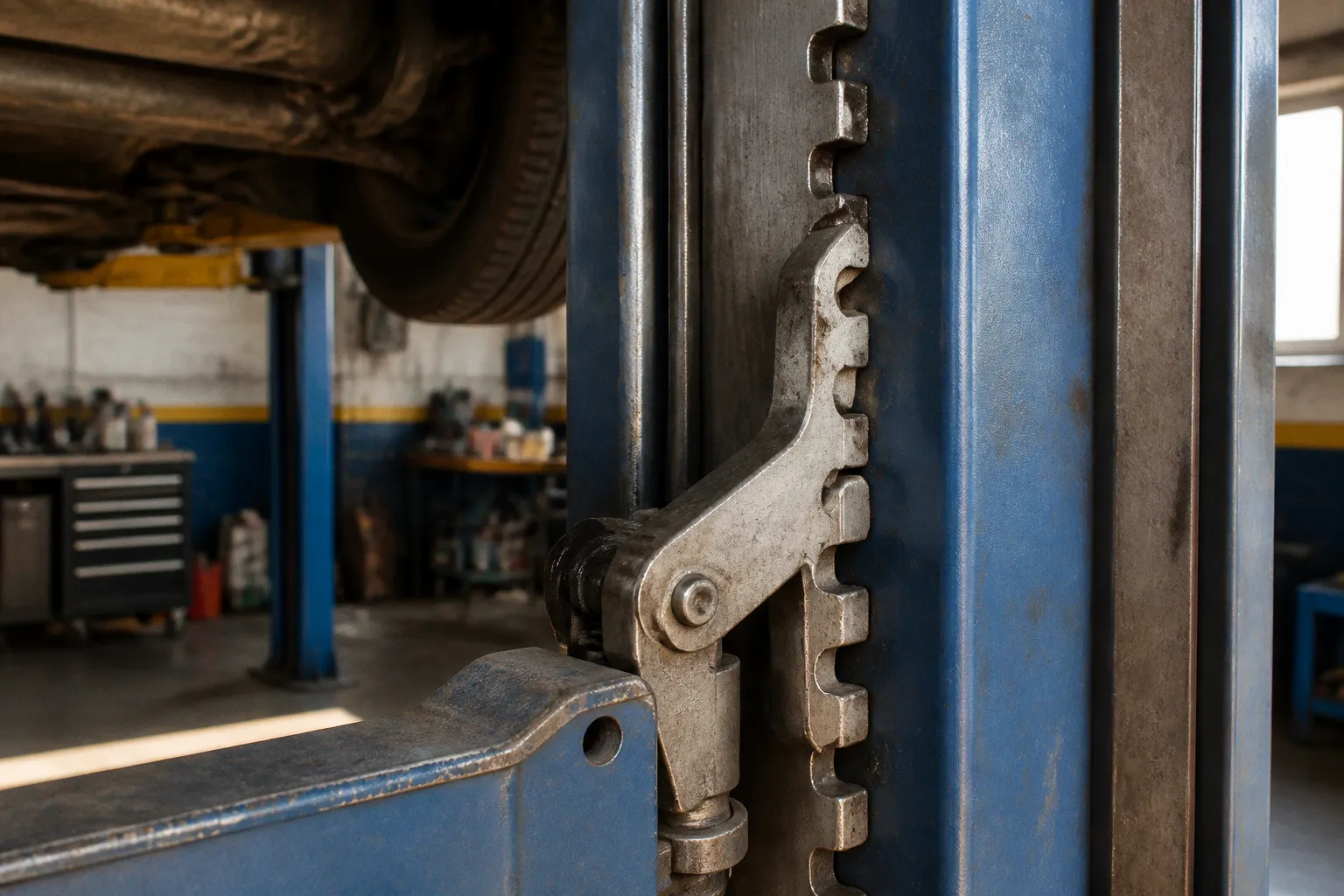
The load-holding function is assigned to mechanical safety locks. Spring-loaded pawls engage notched lock ladders or cam teeth as the carriages rise. If hydraulic pressure is lost, the vehicle does not depend on fluid compression, seal condition, hose integrity, or pump check-valve performance. The mechanical system catches the carriage.
That is the operating principle behind the two post lift safety locks mechanism. Pressure moves the load. Steel supports it.
The Mechanics of Automatic Load-Holding: Pawls and Ratchets
A two-post lift normally has one carriage moving inside each column. The arms attach to these carriages. The vehicle load is distributed between the columns through the arms, adapters, frame contact points, and the lift’s equalization system.
A safety lock is fitted to each carriage or column assembly. Its primary parts are simple:
- A spring-loaded pawl or latch.
- A fixed notched ladder, rack, or cam-tooth track.
- A release cable, lever, pneumatic actuator, or electronic release system, depending on the model.
- A return spring that places the pawl in the engaged position when the release force is removed.
During ascent, the pawl rides over the teeth. Each tooth produces a short mechanical reset. The spring forces the pawl back toward the locking surface after every step.
The lock does not need hydraulic pressure to remain engaged. This matters. A hydraulic cylinder can generate force only while its pressure circuit remains intact. A steel pawl seated behind a tooth does not require pressure to remain in that position.
Lock spacing varies. Common engagement intervals are approximately 3 to 6 inches. Some designs use a tighter cam or tooth arrangement with roughly 0.75-inch tooth-to-tooth spacing. The smaller the spacing, the shorter the possible carriage movement before the pawl reaches a load-bearing surface.
This is not the same as saying that every lift stops within the same distance. The result depends on:
- Tooth spacing.
- Pawl geometry.
- Carriage movement.
- Spring condition.
- Lock alignment.
- Whether both columns engage simultaneously.
- Whether the load is centered and within the rated capacity.
A lock is a load-holding device. It is not a substitute for correct arm placement or rated-capacity control.
How a car lift safety latch operates during ascent
The sequence is mechanical:
1. Hydraulic pressure raises the cylinders or carriage assembly.
2. The pawls contact the inclined surfaces of the ladder teeth.
3. Each pawl is pushed away from the tooth face.
4. The return spring forces the pawl back toward the rack.
5. When the carriage reaches the next notch, the pawl seats behind the tooth.
6. The process repeats through the full lifting range.
The pawl should be able to move freely. It must not bind against the column, remain partially retracted, or fail to return under spring force. Dirt, corrosion, bent release hardware, incorrect cable tension, or damaged tooth surfaces can prevent proper engagement.
A release cable that is too tight can hold the pawl away from the rack. A cable that is too loose can prevent complete release when lowering is commanded. Neither condition should be corrected by arbitrary adjustment. The correct setting is manufacturer-specific.
The system must be inspected as hardware, not inferred from sound. A clicking noise during ascent indicates movement over the teeth. It does not prove that the pawl is fully seated or that both columns are locked.
Hydraulic pressure raises the vehicle. Mechanical teeth prevent the vehicle from falling.
Why the Mechanical Lock Is Separate From the Hydraulic Circuit
Hydraulic systems are effective for controlled movement. They are not accepted as the sole load-holding method for a conventional non-screw automotive lift.
Pressure can be lost through several paths:
- A burst hose.
- A failed fitting.
- A damaged seal.
- A leaking valve.
- A failed pump or control component.
- A cylinder fault.
- A gradual pressure loss through internal bypass.
The failure mode is not important to the safety lock. Once the carriage begins to descend, the pawl encounters the next available load-bearing tooth. The mechanical stop converts downward movement into a reaction force carried by the lock, rack, column, and foundation-mounted structure.
The critical distinction is static support versus hydraulic control:
| Function | Hydraulic system | Mechanical safety lock |
|---|---|---|
| Raising the vehicle | Primary function | Not applicable |
| Controlled lowering | Primary function | Not applicable |
| Holding the vehicle after pressure is removed | Not the sole approved support | Primary function |
| Response to hose rupture | Pressure circuit fails | Pawl catches the carriage |
| Energy source required to remain engaged | Hydraulic pressure or valve state | Spring force and mechanical contact |
| Inspection focus | Fluid, hoses, cylinders, valves, seals | Pawls, racks, springs, cables, alignment |
| Load distribution | Controlled through cylinders and equalization | Must be supported by both column locks where designed |
A lock is therefore not a secondary convenience. It is a separate safety layer with a different failure mechanism.
The ANSI/ALI ALCTV standard requires non-screw automotive lifts to include an automatically engaging mechanical load-holding device. The standard was introduced in 1998 and later revised in 2011 and 2017. The requirement addresses the basic hazard directly: a hydraulic failure must not create an uncontrolled free-fall path.
The presence of a lock does not make every lift compliant. Compliance depends on the complete lift design, installation, rated capacity, labeling, inspection, and maintenance condition. A damaged or defeated lock is not a safety lock in functional terms.
What Happens During a Hydraulic Line Rupture
A hose rupture at full extension creates a rapid pressure loss. The carriage can begin to move downward before the hydraulic circuit is isolated. The safety pawl then contacts the next tooth or cam surface.
On tight-spacing designs, the drop before engagement can be less than 1 inch. This is a catch distance, not a free-fall allowance. It must not be treated as an acceptable operating clearance under the vehicle.
The sequence is:
1. A hose, fitting, or hydraulic component fails.
2. Hydraulic pressure drops.
3. The cylinder no longer sustains the intended load.
4. The carriage starts to descend.
5. The spring-loaded pawl rotates or moves into the next available locking position.
6. The pawl bears against the rack tooth.
7. The carriage stops within the available engagement distance.
The force at the lock can be substantial. The vehicle mass, carriage mass, drop distance, geometry, and deceleration rate all affect the load transmitted through the pawl and rack. For that reason, the mechanical lock must not be tested by intentionally dropping a loaded vehicle.
The lock should catch a failure. It should not be used as a dynamic impact device.
Why both columns must be engaged
Many two-post designs use dual-side or double-point safety systems. Each column has a mechanical lock. The two locks must be synchronized and engaged before work begins under the vehicle.
If only one side carries the load after a hydraulic event, the vehicle can become unbalanced. The result depends on the center of gravity, arm geometry, contact points, and the remaining structural support. A single engaged pawl does not guarantee stable support of the entire vehicle.
The correct condition is mechanical support on both sides, with the carriage resting on the intended lock surfaces. Equalization cables or chains help coordinate carriage movement. They do not replace the locking devices.
A vehicle can be level and still not be mechanically locked. Conversely, both pawls can be present while one is blocked by corrosion or maladjustment. Visual confirmation is required.
Resting on the Locks Reduces Hydraulic Stress
A lift can hold a vehicle hydraulically. That does not mean it should remain hydraulically loaded while work is performed.
Once the desired height is reached, the operator should lower the lift slightly until the carriages rest directly on the mechanical locks. This transfers the static load from the hydraulic cylinders, hoses, and seals to the lock structure.
The hydraulic circuit then carries less continuous stress. The effects are direct:
- Cylinder seals are not required to sustain the full static load indefinitely.
- Hydraulic hoses are exposed to less sustained pressure.
- Valve and fitting leakage becomes less relevant to static support.
- Small pressure changes do not create the primary support condition.
- Mechanical support becomes visible through the carriage position and lock engagement.
The exact lowering movement depends on the lift design. The carriage is raised above the lock notch before the release mechanism is operated during a normal lowering sequence. This relieves friction between the pawl and the tooth. Pulling a manual release while the pawl remains heavily loaded can create excessive cable force or prevent clean disengagement.
The safe operating logic is conditional:
- If the vehicle is being raised, the pawls must ratchet into the lock track.
- If the working height has been reached, the vehicle must be settled onto the locks.
- If the vehicle is being lowered, the carriage must first be raised enough to unload the pawls.
- If the release is activated, the operator must control descent through the hydraulic valve.
- If one lock does not release, lowering must stop until the cause is identified.
A lock-release lever is not a load-lifting control. It only retracts the pawls. Hydraulic control remains responsible for lowering.
ANSI/ALI Standards and the Safety Function
ANSI/ALI ALCTV defines the design expectation for automotive lifts: an automatically engaging mechanical device must prevent uncontrolled descent if the hydraulic lifting system fails.
The word automatically is the relevant engineering term. The lock must move into its load-holding position as part of normal ascent. It must not depend on an operator remembering to insert a separate pin at every height. Manual actions can still be required for release, but engagement must occur without a separate manual locking step.
The standard history is useful because it shows the direction of the safety requirement:
| Standard reference | Role in the safety framework |
|---|---|
| ANSI/ALI ALCTV-1998 | Earlier edition establishing requirements for automotive lift construction and safety functions |
| ANSI/ALI ALCTV-2011 | Updated requirements for automotive lift design and operation |
| ANSI/ALI ALCTV:2017 | Later revision used in the current development of lift safety requirements |
| ANSI/ALI ALOIM:2020 | Inspection-oriented standard addressing automotive lift operation and maintenance |
The standard does not eliminate the need for inspection. It defines a safety architecture. The hardware still requires examination for wear, deformation, corrosion, contamination, missing fasteners, and incorrect adjustment.
A certification label is not a condition report. An older lift can have a compliant design and a defective lock. A new lift can be installed incorrectly. The mechanical function must be verified at the equipment in front of the operator.
Inspection Points That Affect Lock Engagement
The safety mechanism should be treated as a precision assembly. The tolerances may be mechanical rather than electronic, but the failure consequences are not minor.
Inspection should include the following:
- Pawl movement through the full available range.
- Return-spring tension and attachment.
- Rack or ladder tooth condition.
- Cam-tooth wear on models using cam-style locking tracks.
- Cracks, bending, or mushrooming at tooth edges.
- Release cable routing and sheath condition.
- Cable attachment points at both columns.
- Synchronization of dual-side release systems.
- Carriage alignment inside each column.
- Debris, grease accumulation, and corrosion around the lock path.
- Fastener presence and retention.
- Evidence that the pawl is contacting the intended load-bearing face.
The lock track should not be modified to improve smoothness. Grinding, drilling, welding, or reshaping a tooth changes the load path. The same applies to replacing springs with non-approved parts or bypassing the lock release because a cable is inconvenient to adjust.
Lubrication requirements vary by manufacturer. Some assemblies require a specified lubricant. Others require a clean, lightly protected surface to avoid attracting abrasive debris. A heavy grease layer can collect dust and prevent the pawl from returning. The service procedure for the specific lift controls this point.
Symptoms of a mechanical lock fault
Certain symptoms require the lift to be removed from service until corrected:
1. One column clicks while the other remains silent.
The two locks may not be synchronized. The silent side may have a seized pawl, broken spring, damaged cable, or obstructed track.
2. The carriage rises but does not settle onto the locks.
The pawls may be held partially retracted. The release system may be over-tensioned.
3. Lowering requires excessive force at the release handle.
The pawls may still be loaded, the release cable may be misrouted, or the lock faces may be damaged.
4. The lift drops several inches before the locks engage.
The tooth spacing, pawl condition, or carriage alignment may be outside the intended operating condition.
5. The vehicle is not level when both carriages appear to be locked.
The load may be incorrectly positioned, the equalization system may be misadjusted, or one lock may be engaging at a different height.
6. A pawl does not return after the release is released.
The spring, pivot, cable, or return path requires inspection before another load is lifted.
The phrase “the lift still works” has no diagnostic value here. A pump can operate while a safety lock is defective.
The Correct Release Sequence
The two post lift safety release mechanism is designed to remove the pawls from the rack during lowering. It is not designed to retract a pawl that is carrying the full vehicle load.
A controlled release sequence is required:
1. The area beneath and around the vehicle is cleared.
2. Tools, stands, transmission jacks, and loose equipment are removed from the lift path.
3. The hydraulic system raises the carriage slightly above the engaged lock notch.
4. The load is removed from the pawl surfaces.
5. The manual, pneumatic, or electronic release is activated according to the lift design.
6. The pawls are confirmed to be retracted.
7. The hydraulic lowering control is operated.
8. The release is returned to its normal position as specified by the manufacturer.
9. The carriage is lowered fully before the vehicle is moved.
The slight upward movement is not optional technique. It reduces contact force at the pawl. If the lock is loaded, the release cable or actuator may be forced against the mechanism. A lever can move without fully retracting both pawls. This is one reason dual-column systems require observation of both sides.
Electronic or pneumatic release systems do not change the mechanical principle. They provide actuation. The pawl remains the load-bearing component.
If the lift begins to descend while the release is not fully reset, the release system must be restored before the next operation. If a pawl remains partially engaged, the carriage can bind or release unevenly.
The lock-release control is a disengagement command. It is not proof that the pawls have cleared both racks.
Mechanical Locks Versus Auxiliary Supports
Mechanical safety locks and auxiliary supports perform different functions.
The integral locks support the lift carriages. They are part of the lift’s engineered load path. Jack stands, support posts, and other auxiliary devices support selected points on the vehicle or chassis. They should not be confused.
A vehicle may require additional support during operations that change its load distribution. Removing an engine, transmission, axle, or major suspension assembly can shift the center of gravity. The lift may remain within its gross capacity while the arm contact geometry becomes unsafe.
The lift’s rated capacity is not the only limit. The following conditions also matter:
- Vehicle center of gravity.
- Contact adapter type.
- Arm reach and angle.
- Frame or pinch-weld condition.
- Lift-point integrity.
- Uneven loading between columns.
- Height of the vehicle roof and underbody.
- Clearance from doors, columns, and overhead structures.
A 9,000-lb lift is not automatically suitable for every vehicle weighing less than 9,000 lb. The load must be placed according to the lift manufacturer’s instructions. A short-wheelbase vehicle and a long-wheelbase vehicle can produce different column and arm loads at the same total mass.
The mechanical locks cannot correct bad geometry. They only retain the carriage within the lift structure after a loss of hydraulic support.
Baseline Parameters for Verification
A repair or adjustment is complete only when the lock system returns to a known operating baseline. The exact values depend on the lift model, but the functional parameters are fixed.
The following conditions must be present:
- Both pawls engage automatically during ascent.
- Engagement occurs at the designed rack or cam intervals.
- Common lock spacing is approximately 3 to 6 inches; tighter systems may use approximately 0.75-inch tooth spacing.
- Both columns reach and hold the selected height.
- The vehicle settles onto the mechanical locks after a controlled lowering movement.
- No hydraulic pressure is required as the sole support condition.
- Both release paths retract the pawls when the carriage is unloaded.
- Pawls return to the engaged position when the release command is removed.
- No lock tooth is cracked, bent, excessively worn, or modified.
- No carriage movement occurs beyond the designed catch distance during a controlled inspection procedure.
- The lift remains within its rated capacity, commonly 9,000 to 11,000 lb for many two-post units, with larger commercial equipment rated approximately 15,000 to 18,000 lb.
The less-than-1-inch catch distance cited for tight-spacing designs describes the expected movement before the safety cam arrests the carriage during a hydraulic failure. It is not a clearance target for normal work. The intended working condition is a vehicle settled on engaged locks with no reliance on hydraulic pressure alone.
A two-post lift is safe because its systems are separated. Hydraulic components provide motion. Mechanical locks provide retention. Equalization hardware coordinates the columns. The foundation carries the structural reaction. Operator procedure preserves the intended load path.
When those conditions are verified, the safety latch is not an accessory and not a reassuring sound during ascent. It is the final mechanical equation in the system: loss of pressure produces carriage movement; carriage movement produces pawl engagement; pawl engagement produces load retention.