Hydraulic jack check valves: how they hold vehicle weight
A hydraulic floor jack that drops 1–5 mm/min under a 50% rated load has an internal pressure-retention fault. The failure is not explained by the handle, the lifting arm, or the visible ram alone.
Aldous Moorland·Updated: August 12, 2026·15 min read
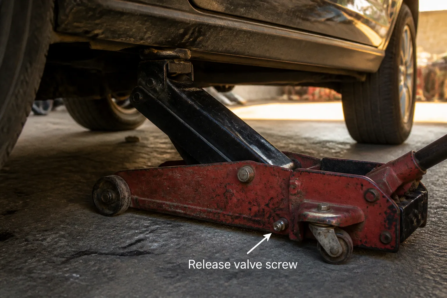
The hydraulic car jack internal mechanism depends on directional valves, a release valve, and ram seals. If one of those paths permits reverse flow, stored pressure is lost and the vehicle descends.
The lifting force is generated by hydraulic pressure acting on the main cylinder ram. The pressure is retained between pump strokes by two one-way check valves. One controls fluid entering the pump chamber. The other controls fluid entering the main cylinder. Their operation is simple. Their condition is decisive.
The hydraulic circuit has one job: permit flow in one direction
A conventional floor jack uses a reservoir, a small pump chamber, a main cylinder, an inlet check valve, an outlet check valve, and a release valve. The pump handle moves a small piston. The piston does not directly support the vehicle. It transfers fluid into the larger cylinder, where pressure acts on the ram.
The pressure relationship is defined by force and area:
Pressure = force ÷ area
The pump piston has a relatively small area. The main ram has a larger area. A modest force applied to the pump piston can therefore generate a large lifting force at the main ram, provided the fluid is incompressible and leakage is controlled.
The hydraulic jack check valve function is directional isolation. Each valve must open when flow is required and close when reverse flow would reduce cylinder pressure.
Pump handle upstroke
During the upstroke, the pump piston moves away from the pump chamber.
If the chamber pressure falls below reservoir pressure, the inlet check valve opens. Fluid is drawn from the reservoir into the pump chamber.
At the same time, the outlet check valve remains closed. This prevents pressurized fluid already present in the main cylinder from returning through the pump circuit.
The required cracking pressure is low. Typical values range from 3 to 10 PSI, or approximately 0.2 to 0.7 bar. The valve does not need significant pressure to open during suction. It needs a clean seat and unrestricted movement.
Pump handle downstroke
During the downstroke, the pump piston compresses the fluid in the pump chamber.
The inlet check valve closes. This blocks the path back to the reservoir.
If pump-chamber pressure exceeds main-cylinder pressure, the outlet check valve opens. Fluid is forced into the main cylinder. The ram extends. The vehicle rises.
When the handle stroke ends, the outlet valve closes again. The pressure in the main cylinder is then isolated from the pump chamber and reservoir.
That sequence repeats for every stroke:
1. The upstroke opens the inlet path and fills the pump chamber.
2. The downstroke closes the inlet path and opens the outlet path.
3. The outlet path closes when the stroke ends.
4. The main cylinder retains pressure between strokes.
A check valve that opens in both directions cannot retain load. A check valve that remains closed in both directions cannot lift the ram. A check valve with a damaged seat may lift the vehicle but allow a slow descent.
The jack holds weight because reverse fluid movement is blocked after every pump stroke. The pump creates pressure. The check valves preserve it.
Steel balls, springs, and machined seats
Most hydraulic floor jack check valves use a hardened steel ball pressed against a machined seat. The ball is the moving closure element. The seat is the sealing surface. A spring or gravity applies the closing force.
The ball may be manufactured from hardened steel in the approximate HRC 58–62 range or from stainless steel such as 440C. The seat may be machined into mild steel or brass. The materials have different hardness values by design. The ball must remain dimensionally stable. The seat must provide a continuous ring of contact.
The sealing interface is small. That does not make it unimportant. A small groove, dent, corrosion mark, or particle trapped between the ball and seat creates a leakage path. At high hydraulic pressure, a path that is invisible to the eye can pass enough fluid to lower the ram.
The check valve contains several failure points:
- A steel ball can be pitted, flattened, or contaminated with metal debris.
- A brass or mild-steel seat can be marked by the ball after repeated overloads.
- A spring can weaken, break, or become displaced.
- A valve bore can contain varnish, sludge, or fragments from a damaged seal.
- A release valve can remain partially open and imitate a failed check valve.
- A ram seal can bypass fluid internally even when both check valves close correctly.
The exact ball diameter and spring rate vary by jack manufacturer and capacity. Replacement parts cannot be selected reliably by visual similarity alone. A ball that appears correct may have the wrong diameter, hardness, or seat geometry.
Why the valve can hold several tons with a light spring
The spring does not hold the vehicle's full weight. System pressure does that.
The spring only returns the ball to the seat and maintains contact when the pressure differential is low or reversed. Once pressure rises on the cylinder side, the hydraulic force presses the ball into the seat. The sealing load is therefore generated primarily by system pressure, not by spring preload.
The spring must still be correct. If its force is excessive, the valve may not open at the required pressure during the suction stroke. If its force is inadequate, the ball may not close before reverse flow begins. The typical cracking-pressure range of 3–10 PSI illustrates the narrow requirement: opening resistance is low, but closure must remain positive.
Contamination is a hydraulic fault, not a cosmetic fault
Hydraulic oil carries particles into small passages. A particle on the check-valve seat prevents a complete seal. The jack may then show one of three patterns:
- The ram rises normally but drops under load.
- The jack rises slowly and requires additional handle strokes.
- The ram will not rise because the outlet valve cannot build pressure.
The correct diagnostic response is disassembly according to the manufacturer's service design, followed by inspection of the ball, seat, spring, and fluid. Random adjustment of the release mechanism is not a substitute for inspection. The release valve controls lowering. It does not correct a damaged check-valve seat.
The overload relief valve limits pressure
A hydraulic jack is not permitted to generate unlimited pressure. An overload relief valve is often integrated into the pump or valve block. Its purpose is to open when pressure exceeds the intended operating limit.
A typical relief setting is approximately 125% of maximum working pressure. If the jack is rated for a defined working pressure, the relief valve opens above that threshold and diverts fluid rather than allowing pressure to continue rising without control.
This valve creates a separate diagnostic path.
If the relief valve opens below the expected load, the jack may stop lifting while the pump handle continues to move. If the valve is contaminated or incorrectly adjusted, pressure may be bypassed into the reservoir. The symptom can resemble a leaking outlet check valve.
If the jack lifts its rated load and then slowly lowers after the handle stops, the relief valve is not the first component to condemn. The outlet check valve, release valve, and ram seals must be separated by testing.
The overload valve does not replace vehicle support equipment. A hydraulic jack is a lifting device. It is not a permanent support. Once the vehicle has been raised, correctly rated jack stands must carry the load before work begins beneath the vehicle.
Pressure paths and observed symptoms
| Observed condition | Most likely hydraulic path | Required direction of diagnosis |
|---|---|---|
| Ram does not rise | Inlet valve not filling pump chamber, outlet valve not opening, low fluid level, or severe internal bypass | Confirm fluid level and pump-chamber filling, then inspect both check valves |
| Ram rises with no load but stalls under load | Outlet valve leakage, relief valve opening early, or worn ram seal | Test load retention and inspect the outlet path |
| Ram lowers with handle stationary | Release valve not sealing, outlet check valve leaking, or ram seal bypass | Isolate the release mechanism before reseating a check valve |
| Handle becomes soft or pumps air | Air in the hydraulic circuit or low fluid level | Bleed the system and verify fluid condition |
| Ram rises, then drops slowly | Pressure is escaping from the main cylinder | Measure drop rate and inspect release valve, check valves, and seals |
The table does not identify a component by symptom alone. The same visible behavior can be produced by different internal leaks. The diagnostic objective is to identify the path through which pressure is escaping.
Why a hydraulic jack leaks down under load
The question “why hydraulic jack leaks down” has three primary answers: the release valve is passing fluid, a check valve is passing fluid, or the ram seal is allowing internal bypass.
External oil leakage is not required. A jack can lose height with no visible oil on the floor. Internal leakage moves oil from the pressurized side of the system back toward the reservoir or across the ram seal. The oil remains inside the jack while the ram retracts.
Release valve leakage
The release valve is opened manually to lower the jack. In many designs, turning the handle or release control moves a needle or similar valve element away from its seat.
If the release valve is not fully closed, the pressurized main-cylinder fluid has a return path. Causes include:
- Dirt on the release-valve seat.
- A damaged needle or seat.
- Incorrect assembly.
- A bent control mechanism.
- A valve that has been opened too far and not returned to its operating position.
If the jack lowers immediately after the release control is adjusted, the release mechanism is the first path to inspect. The control must be returned to the manufacturer's specified closed position. Excessive force must not be applied. A damaged valve seat is made worse by forced tightening.
Outlet check valve leakage
The outlet check valve is responsible for retaining the fluid delivered to the main cylinder. If its ball does not seal, pressure can move backward into the pump circuit.
The symptom is often load-dependent. With no load, the ram may appear to hold. Under vehicle weight, the pressure differential becomes large enough to force fluid past the damaged seat.
A drop rate of 1–5 mm/min under a 50% rated load indicates a pressure-retention failure requiring investigation. The rate is not a universal condemnation threshold for every design, but it is a useful reference for identifying a jack that is not maintaining stable height.
Ram seal bypass
The main ram uses seals to prevent fluid from passing around the piston. A worn, cut, hardened, or incorrectly installed U-cup seal permits internal leakage.
Seal selection is dimensional. Common hydraulic seal size systems include AS568 and ISO 3601. The nominal size, material, cross-section, and groove condition must correspond to the original design. A seal with the correct apparent diameter but the wrong cross-section can leak under pressure.
Some seals are rated for pressures up to 5,000 PSI, or approximately 345 bar, without backup rings. That rating is not a universal specification for every seal or jack. It applies only when the seal material, geometry, extrusion gap, temperature, and fluid are compatible.
The ram surface must also be inspected. A scored or corroded rod can damage a new seal during the first extension cycle. Replacing the seal without correcting the surface condition produces a repeat failure.
A jack that lowers without external oil loss has not become mysterious. The pressure has found an internal return path.
A controlled diagnostic sequence
The jack should be tested on a stable surface with the vehicle secured and the load supported by jack stands before any work is performed beneath it. The hydraulic test itself must not be confused with safe vehicle support.
A practical sequence is as follows.
1. Confirm the symptom with a known load.
The jack should be tested below its rated capacity. A 50% rated load provides a useful comparison point. The ram position should be marked, and height loss should be measured over a fixed interval.
2. Inspect the release control.
If the release valve is not fully closed, pressure may be returned to the reservoir. If closing the control changes the drop rate, the release path remains suspect.
3. Check fluid level and fluid condition.
Low fluid can introduce air and prevent the pump from filling. Contaminated or incorrect fluid can interfere with valve movement and seal behavior. Fluid must not be added indiscriminately. The jack's specified hydraulic fluid remains the reference.
4. Bleed trapped air.
Air is compressible. Hydraulic oil is effectively incompressible at the scale involved. A jack containing air may produce a springy handle, incomplete lifting, or unstable ram movement. A typical bleeding procedure uses 10–15 full pump strokes with the release valve operated according to the jack's service instructions.
5. Separate lifting failure from holding failure.
If the jack cannot lift, the inlet valve, outlet valve, pump piston, relief valve, fluid level, and air content are possible causes. If the jack lifts but cannot hold, the release valve, outlet valve, and ram seals become the primary paths.
6. Inspect the valve components.
The ball must be round and free of pitting. The seat must show a continuous contact ring. The spring must be intact and correctly positioned. Debris must be removed without enlarging the valve bore or damaging the seat.
7. Inspect the ram seal and cylinder surface.
A new seal cannot compensate for a scored cylinder or damaged ram. The groove must be clean. The seal must be installed in the correct orientation.
8. Retest at controlled load.
The repair is incomplete until the jack lifts, holds, and lowers through the release valve without abnormal drift.
This sequence prevents a common error: replacing the check valve when the release valve is the actual bypass path.
Reseating a leaking check valve
A leaking check-valve seat can sometimes be restored when the ball is undamaged and the seat is made from a material that can be reformed. A common workshop method uses a brass punch placed on the steel ball while the ball is seated. A light hammer tap reforms the softer seat around the ball's contact area.
The method has strict limits.
The punch must be brass or another material that will not damage the ball. The ball must remain centered on the original seat. The impact must be controlled. Excessive force can deform the seat, fracture a valve block, embed metal into the passage, or create an off-center sealing ring.
The procedure is not a substitute for replacing a damaged ball. If the ball is pitted, visibly flattened, or contaminated with embedded material, reseating the softer metal around a defective ball will not produce a reliable seal.
The repair path is:
1. Remove the valve components without mixing the positions of balls, springs, and plugs.
2. Clean the passage and inspect the ball under magnification.
3. Place the ball on its original seat.
4. Place a brass punch squarely on the ball.
5. Apply a controlled tap to reform the seat.
6. Remove the ball and clean all particles created by the operation.
7. Reinstall the spring and retaining components in their original order.
8. Fill and bleed the jack.
9. Perform a load-holding test.
The check-valve ball diameter must not be assumed. Commercial jacks use different dimensions. If a ball is lost, the correct replacement must be identified from service data or measured components. A random steel bearing is not a controlled repair.
When replacement is the correct decision
A hydraulic jack should be removed from service when the pressure-retention fault cannot be corrected with a verified seal, clean valve components, and a sound release mechanism.
Replacement is preferable when:
- The valve block is cracked.
- The main ram is deeply scored or corroded.
- The release valve seat is damaged beyond cleaning.
- The overload relief valve has been altered without a known specification.
- The jack has been overloaded and its structural members are bent.
- The correct seal dimensions cannot be established.
- The repair requires pressure testing that is not available in the workshop.
A jack can appear mechanically solid while its hydraulic components remain unreliable. The lifting arm and wheels do not confirm pressure integrity. The required evidence is stable height under a controlled load, proper release-valve operation, and correct hydraulic behavior after bleeding.
The baseline that verifies the repair
The final test has four conditions.
The jack must lift the intended test load without excessive handle travel or a soft, compressible feel. The ram must remain stable with the release valve fully closed. Height loss must be measured rather than judged by eye. A drop rate of 1–5 mm/min under a 50% rated load is a clear indication that internal leakage remains and requires further diagnosis.
The release valve must lower the ram only when commanded. The overload relief valve must remain within its specified pressure setting, typically near 125% of maximum working pressure where that design standard applies. No external hydraulic leak may be present at the pump, valve block, ram seal, or reservoir.
The hydraulic car jack internal mechanism is functioning correctly only when its pressure paths are one-directional under load:
- The inlet check valve opens during the pump upstroke.
- The inlet check valve closes during the pump downstroke.
- The outlet check valve opens during the pump downstroke.
- The outlet check valve closes when the stroke ends.
- The release valve remains sealed until lowering is commanded.
- The ram seal prevents internal bypass.
- The overload relief valve limits pressure without opening during the rated lifting test.
Those are the baseline parameters. If any one of them fails, the jack has not been verified.