Brake Proportioning Valves: How Hydraulic Bias Is Regulated
A rear brake circuit reaching 900 psi when the front circuit reaches 1,400 psi is not automatically defective.
Aldous Moorland·Updated: August 14, 2026·15 min read
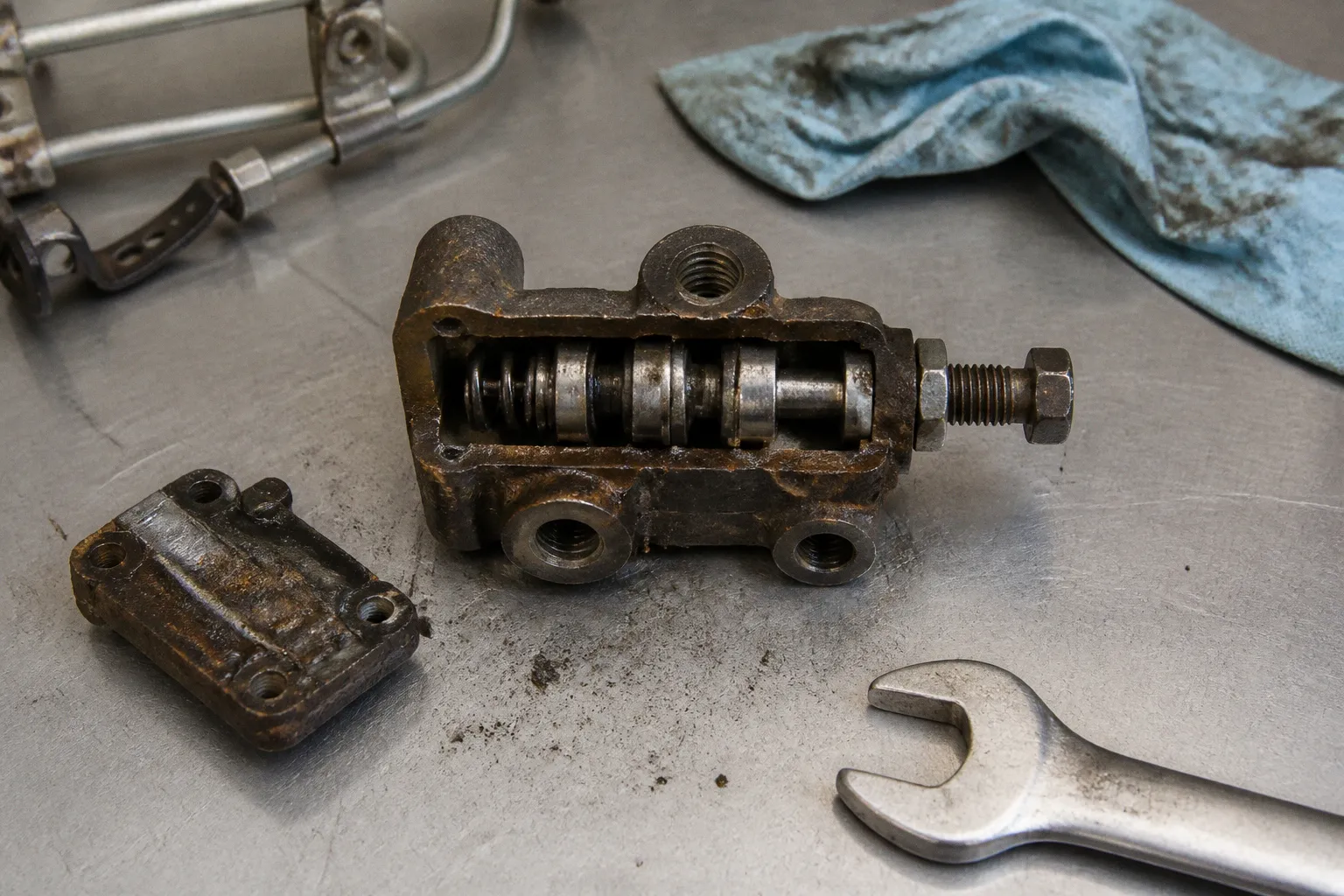
The difference can be the intended result of a brake proportioning valve entering its pressure-reduction range.
The brake proportioning valve working principle is narrow and mechanical. Below a calibrated pressure threshold, front and rear circuits rise together at a 1:1 ratio. Above that threshold, rear pressure continues to increase at a lower rate. The valve does not create pressure. It does not increase front braking force. It limits the rate at which rear pressure rises.
That distinction defines the entire system.
The physics of dynamic weight transfer and rear-wheel lockup
During braking, vehicle load shifts forward. The front axle gains vertical tire load. The rear axle loses it. Available tire grip changes with that load distribution.
A simplified braking event can be described as follows:
- Front tire load increases as deceleration rises.
- Rear tire load decreases by the same transfer force.
- Front tires can accept greater brake torque before sliding.
- Rear tires reach the adhesion limit earlier if hydraulic pressure remains equally distributed.
- A locked rear axle reduces directional stability and can initiate oversteer or rotation.
The rear brakes are not assigned less work because they are mechanically inferior. They are assigned less hydraulic pressure because the rear tires carry less normal load during deceleration.
The exact distribution depends on wheelbase, center-of-gravity height, axle loads, suspension geometry, tire friction, brake rotor diameter, pad coefficient, and vehicle loading. A compact front-wheel-drive import and a loaded rear-wheel-drive truck will not require the same hydraulic bias.
The proportioning valve addresses only one part of that problem: the pressure relationship between the front and rear circuits.
Before the valve reaches its knee point, pressure is transmitted equally:
| Hydraulic condition | Front circuit | Rear circuit | Valve behavior |
|---|---|---|---|
| Below knee point | 300 psi | 300 psi | 1:1 pressure rise |
| At knee point | 500–800 psi on many passenger vehicles | 500–800 psi | Transition begins |
| Above knee point | Continues increasing directly from master-cylinder pressure | Increases at a reduced slope | Rear pressure is proportioned |
| Emergency-stop range | Commonly 1,200–1,500 psi | Lower than front pressure | Rear lockup resistance is increased |
The figures describe hydraulic pressure, not clamp force at the pad. Caliper piston area, pad friction, rotor radius, and tire radius remain part of the complete braking equation.
A proportioning valve does not balance brake pressure equally. It preserves equal pressure only until equal pressure becomes unsafe.
The knee point: how hydraulic pressure thresholds function
The knee point, also called the split point, is the pressure at which rear pressure reduction begins.
Below this point, master-cylinder pressure is passed to the front and rear circuits at the same rate. If the master cylinder produces 400 psi, approximately 400 psi is available in both circuits, assuming negligible line loss and no valve intervention.
Once the threshold is exceeded, the relationship changes. Front pressure continues to follow master-cylinder pressure. Rear pressure rises more slowly.
A simplified pressure relationship can be written as:
Rear pressure = knee-point pressure + reduced slope × pressure above the knee point
For common aftermarket manual valves, the post-threshold slope is often approximately 43% of the additional input pressure. The corresponding reduction in the rate of rear-pressure increase is approximately 57%.
An example:
- Knee point: 600 psi
- Master-cylinder pressure: 1,400 psi
- Pressure above knee point: 800 psi
- Additional rear pressure at a 43% slope: approximately 344 psi
- Rear pressure: approximately 944 psi
The front circuit remains near 1,400 psi, excluding line losses and component compliance. The rear circuit remains active, but its pressure is prevented from following the front circuit at the original 1:1 rate.
This is rear brake pressure regulation. It is not a pressure cut-off. The rear brakes still contribute during a hard stop. They simply contribute within the available rear-tire adhesion.
The threshold must be distinguished from the reduction slope:
- Knee point determines when proportioning begins.
- Slope determines how rapidly rear pressure rises after proportioning begins.
- Maximum rear pressure depends on both values and the valve design.
- Bias describes the resulting front-to-rear braking relationship under a specific load and deceleration condition.
Turning an adjustable valve generally changes the knee point. It does not normally change the slope percentage.
Internal mechanics: differential pistons and spring preload
A conventional hydraulic proportioning valve contains a differential piston, spring, seals, and calibrated passages. The exact housing and piston arrangement varies by manufacturer, but the operating logic remains consistent.
The valve is installed in the rear brake circuit. Front brake pressure must remain unrestricted by the proportioning device. The rear circuit enters the valve and acts against the differential piston. A spring holds the piston in its initial position until hydraulic force exceeds the spring preload and the calibrated threshold.
The sequence is mechanical:
1. Master-cylinder pressure rises in both brake circuits.
2. Rear-circuit pressure acts on the valve piston.
3. Below the threshold, the piston remains in its initial position.
4. Pressure rises through the rear circuit at approximately the same rate as front pressure.
5. At the knee point, hydraulic force overcomes the effective spring preload.
6. The piston moves and changes the available flow geometry.
7. Rear pressure continues to rise, but at the reduced slope.
The valve does not need to “sense” wheel speed. It does not know whether a tire is rotating. It reacts to hydraulic force.
This separates it from ABS. An anti-lock braking system uses wheel-speed sensors, an electronic control unit, and solenoid valves to modulate pressure during an incipient lock event. A mechanical proportioning valve applies a predetermined pressure relationship before wheel lock occurs. It cannot compensate for ice on one side of the road, different tire compounds, or an incorrectly sized rear brake system.
A combination valve may contain several functions in one body:
- Front or rear pressure metering.
- Rear pressure proportioning.
- Hydraulic warning switch for circuit imbalance.
- Pressure-differential piston.
- In some designs, residual-pressure functions.
The external housing can therefore resemble a simple proportioning valve while performing several hydraulic tasks. The service manual remains the authority for port identification and circuit routing.
What happens when the valve is installed incorrectly
The proportioning valve must be connected to the rear brake circuit. If it is placed in a front circuit, front brake pressure will be restricted. That changes the intended braking balance and can extend stopping distance.
Incorrect plumbing can also produce misleading symptoms:
- Rear brakes remain too aggressive because the valve is bypassed.
- Front brakes receive reduced pressure because the valve is installed in the wrong line.
- Bleeding becomes ineffective because the ports do not match the internal circuit.
- The warning switch in a combination valve reports a false hydraulic imbalance.
- The valve appears defective when the actual fault is reversed inlet and outlet routing.
A valve that is merely present in the engine bay is not necessarily functioning in the correct circuit.
Adjustable proportioning valves: tuning the pressure threshold
Manual adjustable valves are used when factory hydraulic bias no longer matches the vehicle configuration. Common causes include:
- Rear disc conversion.
- Different rear caliper piston area.
- Larger rear rotors.
- Nonstandard pad friction.
- Coilover or spring changes that alter ride height.
- Competition tires with higher available grip.
- Removal or replacement of a load-sensing mechanism.
- Significant changes in vehicle mass distribution.
The adjustment typically changes spring preload. Increasing preload moves the knee point higher. More master-cylinder pressure reaches the rear brakes before reduction begins.
A typical adjustment logic is:
- Knob turned inward: higher spring preload, higher knee point, more rear pressure before proportioning.
- Knob turned outward: lower spring preload, lower knee point, earlier rear-pressure reduction.
The exact direction must be confirmed from the valve manufacturer. Thread direction, knob orientation, and scale markings are not universal.
The adjustment range can be substantial. A manual valve may shift the threshold from approximately 300 psi to approximately 1,000 psi, depending on its design. That does not mean the valve can provide any arbitrary rear pressure. The post-knee slope remains largely fixed in common aftermarket designs, often near 43% of additional input pressure.
A valve with a 57% reduction in slope is therefore not adjustable from 0% to 57% reduction. The adjustment shifts the point at which that reduction begins.
A controlled tuning sequence
Adjustments must be made from a known baseline. Random knob movement changes the system without identifying the resulting hydraulic relationship.
The following sequence provides a usable diagnostic structure:
1. Confirm the hardware.
The master cylinder, front calipers, rear calipers, rotors, pads, tires, and valve must match the intended vehicle configuration. A proportioning valve cannot correct a mismatched caliper piston area or a mechanically seized rear caliper.
2. Confirm circuit routing.
The valve must be installed only in the rear circuit. Port direction must match the manufacturer’s specification. The front circuit must remain unrestricted.
3. Restore mechanical condition.
Pad contact, caliper slide movement, piston travel, rotor condition, wheel bearing play, brake hose integrity, and parking-brake adjustment must be verified before hydraulic bias is tuned.
4. Set a conservative starting point.
Rear pressure should be reduced early rather than late when the initial configuration is unknown. Excess rear bias is the more dangerous failure mode because rear lockup can destabilize the vehicle.
5. Evaluate on a controlled surface.
Braking should be applied progressively. Rear lockup before front lockup indicates excessive rear pressure. A front lockup condition with weak rear contribution indicates insufficient rear pressure or a rear mechanical fault.
6. Change one variable.
The valve should be adjusted in small, recorded increments. Tire pressure, cargo, road surface, and vehicle temperature should not be changed between comparisons.
7. Recheck under the actual load condition.
A vehicle that behaves correctly with one driver may exhibit a different bias with passengers, cargo, or a changed fuel load.
The target is not equal tire slip. The target is stable braking with the front axle reaching its adhesion limit slightly before the rear axle under the relevant operating conditions.
The correct setting is not the one that produces the strongest rear braking. It is the one that preserves directional stability at the limit of adhesion.
Load-sensing systems and mechanical linkage integration
Many production vehicles use a load-sensing proportioning valve rather than a fixed manual valve. The system changes the rear pressure threshold according to rear-axle load and suspension height.
A mechanical linkage connects the chassis to the rear axle or suspension assembly. As the vehicle is loaded, the rear body height changes relative to the axle. The linkage moves the valve mechanism and changes the knee point.
The purpose is direct:
- Light rear load produces lower rear braking demand.
- Heavy rear load increases available rear-tire traction.
- The valve allows more rear pressure when the rear axle is carrying greater weight.
- The threshold is reduced when the rear axle unloads during braking.
This arrangement is sensitive to ride height and linkage position. Lowering springs, worn bushings, bent brackets, incorrect replacement shocks, or seized linkage joints can shift the valve away from its designed operating range.
The vehicle may then display one of two opposite conditions:
- Rear brakes receive too little pressure under load, reducing braking contribution.
- Rear brakes receive too much pressure when lightly loaded, increasing rear-lock tendency.
The linkage is not an optional accessory. On a vehicle designed around a load-sensing valve, its position is part of the hydraulic calibration.
A static visual check is insufficient. The service procedure may specify ride height, linkage angle, spring position, or pressure measurements at defined pedal forces. Without those specifications, the valve cannot be calibrated accurately by appearance alone.
Diagnosing a brake proportioning valve fault
A proportioning valve is often blamed when the actual fault exists elsewhere in the brake system. Hydraulic bias should be diagnosed only after mechanical and bleeding faults have been excluded.
Rear wheels lock too early
If both rear wheels lock before the fronts, the likely categories are:
- Knee point set too high.
- Incorrect manual-valve adjustment.
- Load-sensing linkage positioned for a heavier load than the vehicle is carrying.
- Rear calipers or wheel cylinders with excessive effective area.
- Rear friction material with a higher coefficient than specified.
- Incorrect master-cylinder or valve configuration.
- Rear tires with reduced grip.
The valve should not be adjusted until caliper operation and tire condition have been verified. A seized front caliper can produce an apparent rear-bias problem because the front axle is not generating its expected braking torque.
Rear brakes contribute too little
Weak rear braking can result from:
- Knee point set too low.
- Restricted rear hose or line.
- Air remaining in the rear circuit.
- Seized caliper slides.
- Incorrect pad installation.
- Parking-brake mechanism not releasing or not adjusting.
- Load-sensing linkage stuck in a low-pressure position.
- Rear rotor or drum contamination.
A pressure reduction valve cannot be diagnosed from pad wear alone. Uneven wear identifies a mechanical or hydraulic imbalance, but it does not identify the valve’s knee point.
Hydraulic pressure measurement
Pressure gauges installed at the front and rear circuits provide direct evidence. Measurements must be taken with suitable adapters, clean fittings, and a secure test setup. Brake fluid injection risk is present whenever a line is opened.
The expected pattern is:
- Below the knee point: front and rear pressures rise together.
- At the knee point: rear pressure begins to diverge.
- Above the knee point: front pressure continues rising faster.
- With a correctly functioning fixed valve: the pressure relationship remains repeatable.
For an aftermarket valve with a nominal 600 psi knee point and approximately 43% post-knee slope, a measured front pressure of 1,400 psi would be expected to produce rear pressure near 944 psi under the simplified relationship. Actual results depend on gauge accuracy, temperature, seal friction, line compliance, and the valve’s manufacturing tolerance.
A reading that remains 1:1 beyond the specified threshold indicates one of several conditions:
- The valve is bypassed.
- The wrong valve is installed.
- The valve is plumbed into the wrong circuit.
- The piston is seized in the open position.
- The measurement point is not on the regulated rear circuit.
- The valve specification has been misunderstood.
A reading that drops abruptly to near zero is not normal proportioning behavior. That indicates restriction, trapped air, a failed component, or a circuit problem.
The valve is not tested by electrical resistance
A mechanical proportioning valve has no meaningful ohm specification. If a combination valve includes a hydraulic warning switch, the switch can be checked electrically for continuity or open circuit according to its service procedure. The hydraulic regulator itself is evaluated through circuit routing, physical condition, and pressure response.
This distinction prevents a common diagnostic error: treating the warning switch as proof that the proportioning mechanism is functioning. The switch reports pressure differential. It does not confirm the knee point or the post-knee slope.
Brake bleeding and valve behavior
Air in the rear circuit changes pedal travel and pressure transmission. It can make the brake pedal feel soft while creating the impression that the proportioning valve is reducing rear pressure excessively.
The bleeding sequence must follow the vehicle manufacturer’s procedure. Some combination valves require the warning-switch piston to be centered. Some ABS-equipped systems require scan-tool activation of the hydraulic modulator. A manual bleeding procedure that ignores the ABS unit may leave air trapped in the modulator.
The following conditions must be separated:
- Soft pedal: air, hose expansion, caliper movement, master-cylinder bypass, or excessive bearing play.
- Rear lockup: excessive rear bias, low rear tire grip, or incorrect rear hardware.
- Uneven braking: seized hardware, contaminated friction material, restricted hose, or caliper imbalance.
- Long pedal with stable pressure: mechanical travel or air.
- Hard pedal with low braking force: vacuum assist, booster, master-cylinder sizing, or friction-level issue.
The proportioning valve changes pressure slope. It does not remove air, shorten caliper travel, or correct a soft pedal.
Fixed valves, adjustable valves, and load-sensing valves
These designs solve different calibration problems.
| Valve type | Pressure threshold | Post-threshold behavior | Typical application |
|---|---|---|---|
| Fixed mechanical valve | Factory-set knee point | Fixed reduction slope | Original vehicle configuration |
| Adjustable manual valve | User-adjustable knee point | Usually fixed reduction slope | Modified brake systems and competition tuning |
| Load-sensing valve | Mechanically varied with ride height and axle load | Defined by valve design | Production vehicles with variable rear loading |
| ABS hydraulic modulator | Electronically commanded | Pressure can be increased, held, or released repeatedly | Wheel-lock prevention |
A fixed valve is not automatically inferior to an adjustable valve. It is calibrated for a defined vehicle. An adjustable valve becomes useful when the vehicle no longer matches that definition.
A manual valve is also not a substitute for ABS. It cannot detect individual wheel slip. It cannot release pressure from one wheel while maintaining pressure at another. It cannot respond to changing surface friction during a single stop.
Final verification: the baseline parameters
A brake proportioning valve repair or adjustment is verified only when the hydraulic and vehicle behavior agree.
The baseline should include:
- Correct valve location in the rear brake circuit.
- Unrestricted front-circuit flow.
- No external hydraulic leakage.
- Correct brake-fluid level and specified fluid type.
- Firm pedal after bleeding.
- Free movement of caliper pistons and slides.
- Correct rear parking-brake adjustment.
- Correct ride height and load-sensing linkage position, where fitted.
- Recorded knee point or manufacturer-specified pressure relationship.
- Rear pressure rising more slowly than front pressure above the knee point.
- No premature rear lockup during controlled braking.
- Front lockup occurring before rear lockup when the system is tested near the traction limit.
- Repeatable results with the intended vehicle load.
For a common aftermarket design, a pressure reduction slope near 57% and an effective post-knee slope near 43% may be expected. That value is not universal. Proprietary OEM combination valves require the relevant factory specification.
The working principle remains fixed: pressure rises at 1:1 until the knee point, then rear pressure rises more slowly. Every valid diagnosis, adjustment, and repair must return to that relationship.