CAN bus networks use differential voltage to prevent noise
A typical scenario that walks into the shop: a late-model European sedan arrives with the scanner reporting "U0073 – Control Module Communication Bus Off." The fault log shows no other codes. The gateway module is non-responsive to diagnostic requests.
Aldous Moorland·Updated: August 07, 2026·14 min read
Battery voltage is stable at 12.6 V, and the fuses are intact. None of this should be treated as a verified field case; it is a composite example of the kind of presentation that drives the diagnostic approach described in this article.
That pattern does not prove the vehicle has a signal-integrity failure, but it changes the direction of the diagnosis. A bus-off condition can be caused by wiring, termination, a damaged transceiver, a shorted control unit, or power and ground problems that destabilize a module. The scanner has identified the symptom, not the physical cause. The next step is not to replace the gateway. It is to examine the CAN network itself, starting with a multimeter and an understanding of the voltage relationships that allow the bus to reject noise.
The Physics of Differential Signaling in Import Multiplex Wiring
Modern European and Asian vehicles use multiplex wiring to reduce the number of separate wires required between electronic control units. The engine controller, transmission controller, ABS module, airbag system, climate control, body controller, instrument cluster, gateway, and other devices exchange information over shared communication networks rather than receiving a dedicated wire for every individual message.
The Controller Area Network, or CAN bus, is one of the most common of these networks. It is not simply a pair of wires carrying two independent digital voltages. Its physical layer is designed around the voltage difference between the wires.
The pair consists of:
- CAN High (CANH)
- CAN Low (CANL)
The receiver primarily evaluates the differential voltage:
Vdiff = CANH − CANL
The voltage of either conductor relative to chassis ground still matters during diagnosis, but it is not the value that directly represents the CAN bit. A healthy network can tolerate some movement in its common voltage because both conductors are intended to move together when external interference reaches them.
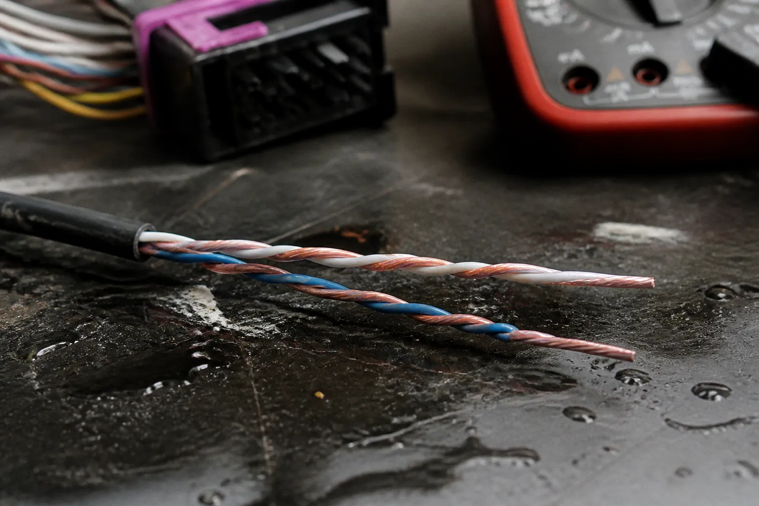
This is where the twisted pair earns its place. The two conductors are kept close together and repeatedly exchanged in position along the cable. An electromagnetic field from an ignition system, alternator, electric motor, relay, or other source tends to induce a similar voltage in both conductors. If interference adds approximately 1 V to CANH, it also adds approximately 1 V to CANL. The common-mode voltage has shifted, but the difference between the lines has changed very little.
The receiver rejects much of that common-mode disturbance and continues to recognize the intended differential signal. The rejection is not unlimited. Excessive common-mode voltage, poor grounding, damaged shielding, bad routing, or a severe transient can still push a transceiver outside its operating range. Differential signaling is a method of reducing noise sensitivity, not a guarantee that any damaged wiring will continue to work.
The cable geometry is only one part of the physical layer. The transceivers, the characteristic impedance of the wiring, the two end-of-line termination resistors, connector quality, and the layout of the network all affect whether the signal arrives cleanly at every module. A vehicle can have correct nominal voltage at the diagnostic connector and still suffer communication errors because a connector is introducing intermittent resistance or a branch is creating reflections.
Decoding Recessive and Dominant States: Voltage Thresholds Explained
CAN communication uses two bus states: recessive and dominant. In the familiar high-speed CAN arrangement, the recessive state is not created by forcing CANH high and CANL low. The lines are released by the transceivers and settle near the common bias voltage.
Typical nominal values are:
| Bus state | CANH to ground | CANL to ground | Differential voltage |
|---|---|---|---|
| Recessive / idle | Approximately 2.5 V | Approximately 2.5 V | Near 0 V |
| Dominant / active | Approximately 3.5 V | Approximately 1.5 V | Approximately 2.0 V |
The exact readings depend on the transceiver design, the network state, the measuring instrument, and the vehicle manufacturer's implementation. These values are useful diagnostic references, not a substitute for the wiring diagram or the specifications for the particular network.
In the recessive state, CANH and CANL should be approximately equal. There is no requirement for CANH to sit at a higher potential than CANL while the bus is idle. Both conductors are nominally around 2.5 V, so a small difference between them can come from measurement tolerance, bias circuits, network activity, or the way a digital multimeter averages a changing signal.
When a node transmits a dominant bit, its CAN transceiver drives the pair in opposite directions. CANH moves upward and CANL moves downward. The resulting differential voltage is large enough for the receiving nodes to identify the dominant state. A dominant bit overrides a recessive bit, which allows CAN arbitration to work without a separate collision-detection wire.
At idle, a healthy CAN pair is balanced: CANH and CANL are approximately equal. The meaningful separation appears when the bus drives a dominant bit.
A multimeter can provide a useful first look at these states, but it cannot show the timing of the signal. On a live network, the display may settle at an average value somewhere between the recessive and dominant levels. A reading around 2.5 V on each line does not necessarily mean that no communication is taking place. Conversely, an apparently plausible average voltage does not prove that the waveform has clean edges or that every module can interpret it.
For a basic voltage check, measure each line to a reliable chassis or battery negative reference. On many high-speed CAN systems, both lines will remain broadly within the low-single-digit voltage range during normal operation, often around 2.0–4.0 V depending on bus activity. The two readings should be considered together:
- CANH and CANL both close to one another: consistent with a recessive or averaged bus condition.
- CANH generally higher and CANL generally lower during activity: consistent with dominant signaling.
- One line fixed near ground or battery voltage: possible short, failed transceiver, damaged wiring, or loss of the network bias.
- One line substantially different from the other while the bus is supposed to be idle: possible loading fault, short, incorrect termination, or a module that is not releasing the bus.
Do not diagnose reversed wires from a single multimeter comparison. During dominant traffic, CANH is expected to be above CANL. During the recessive state, they should be approximately equal. A scope, resistance test, and wiring inspection are needed to establish whether the pair has actually been crossed or miswired.
Physical Layer Diagnostics: Measuring Resistance and Idle Voltages
Resistance testing is most useful with the vehicle powered down and the network allowed to discharge. Turn the ignition off, remove the key or keep the key away from the vehicle where applicable, and wait for the modules to enter their sleep state. On some vehicles, opening a door or repeatedly waking the vehicle can change the measurement. The service information may specify a sleep period or a procedure for preventing wake-up.
At a diagnostic connector, pins 6 and 14 commonly provide access to high-speed CANH and CANL. That arrangement is widespread, but it should be confirmed against the vehicle's pinout. Some import vehicles have multiple CAN networks, gateways, diagnostic switches, or manufacturer-specific routing. Measuring the wrong pair can produce a perfectly reasonable resistance value that says nothing about the network causing the fault.
With power removed, measure resistance between CANH and CANL. A conventional network with two 120-ohm termination resistors in parallel will measure close to 60 ohms. A practical reading in the approximate 45–65 ohm range can be consistent with a connected, terminated network, although the acceptable range depends on the design and the accuracy of the test conditions.
The interpretation is more useful when combined with the circuit layout:
- Approximately 60 ohms: both nominal 120-ohm terminators appear to be present, with no obvious short between the lines.
- Approximately 120 ohms: one terminator may be missing, disconnected, or isolated by an open circuit.
- A very low resistance: possible short between CANH and CANL, a failed transceiver, or an attached module loading the network.
- Very high resistance or OL: possible open circuit, disconnected connector, broken conductor, or a network that is not connected to either termination resistor.
- A value that changes when harnesses or connectors are moved: an intermittent connection is more likely than a stable design characteristic.
The two terminators are placed at the physical ends of the bus. They are not necessarily located in the same type of module on every vehicle. One may be integrated into an engine controller, gateway, ABS module, or another end node; the other may be in a different control unit or a separate part of the harness. A wiring diagram is essential before unplugging modules at random.
A 60-ohm reading does not clear the entire network. Two resistors can remain in parallel even when a branch contains corrosion, a marginal crimp, or a module that fails only when hot. It is also possible to measure the correct resistance at the OBD connector while a downstream branch is intermittently losing communication. For that reason, divide-and-isolate testing is often more productive than replacing the first non-responsive module.
With the vehicle powered, check the voltage on both lines to ground. Do this at the diagnostic connector first, then at accessible network points if the fault is intermittent. Compare the readings with the manufacturer's wiring information and with the state of the network. A vehicle in sleep mode, a vehicle during wake-up, and a vehicle actively transmitting can show different meter readings.
Power and ground checks belong in the same stage. A control module with a poor ground can distort its CAN output and create multiple communication codes, even though the CAN pair itself is intact. Check voltage drop under load rather than relying only on continuity. A wire that passes an ohmmeter test with no load can still fail when current flows through a corroded terminal.
Identifying Communication Failures via Oscilloscope Waveform Analysis
A multimeter shows average or slowly changing voltage. CAN is a timed digital network, so many faults remain invisible until the waveform is examined. Oscilloscope testing of CAN requires attention to both the connection method and the reference point.
The cleanest method is a differential probe connected across CANH and CANL. A two-channel scope can also be used with one probe on each conductor and a math trace configured as CH1 minus CH2. The probe grounds must be connected safely and correctly. Connecting a grounded bench oscilloscope to an unsuitable vehicle point can create a short to chassis or damage the instrument. Follow the scope manufacturer's automotive measurement guidance.
On a healthy high-speed CAN network, the differential trace should show two principal levels:
- A recessive level close to 0 V differential.
- A dominant level near 2 V differential.
The single-ended traces should move in opposite directions during a dominant bit: CANH rises while CANL falls. The transitions should be clean, and the dominant plateau should remain reasonably stable. The recessive level should return close to zero differential when the bus releases.
The bus speed affects how much time is available for the signal to settle. A network may appear acceptable at a lower bit rate yet fail at a higher one because rounded edges, ringing, or delayed settling occupy a larger portion of each bit. Common high-speed applications use rates such as 125, 250, or 500 kbit/s, but the correct rate is vehicle- and network-specific. The scope's time base should be chosen so that individual bits and groups of bits can be inspected rather than viewed only as an indistinct band.
Several waveform patterns are especially informative:
- Slow edges or rounded slopes: may indicate excessive capacitance, an added device, a long or improperly branched harness, water intrusion, or a transceiver that is no longer driving correctly.
- Ringing after a transition: often points toward impedance discontinuity, poor termination, an excessive stub, a connector problem, or a wiring repair that changed the physical geometry.
- Reduced differential amplitude: can result from resistive corrosion, a weak transceiver, supply-voltage problems at a node, a partial short to another circuit, or a module loading the bus.
- A dominant state that does not release: suggests a node stuck dominant, a shorted conductor, or a failed transceiver. This condition can prevent all other modules from communicating.
- Unequal single-ended movement: may indicate common-mode problems, a poor ground reference, a damaged twisted pair, or one conductor with abnormal resistance.
- Narrow spikes or bursts of high-frequency noise: can be associated with switching loads, ignition interference, charging-system problems, or an unstable supply. The timing of the disturbance matters: noise synchronized with an actuator or alternator load is more useful than a generic label of "EMI."
- Intermittent dropouts when the harness moves: point toward connectors, crimps, flex points, or water entry rather than a protocol problem.
A scope can also help distinguish a bus problem from a module problem. If the differential signal is clean at the gateway but distorted at a branch connector, the harness or branch module becomes more suspicious. If the waveform collapses only when a particular control unit is connected, disconnecting that unit under the correct service procedure can confirm that it is loading the network. Never disconnect modules indiscriminately on a powered vehicle; some systems can generate additional faults or lose initialization data.
Error codes provide context but should not be treated as waveform evidence. A U-code may be stored by several modules because one node stopped transmitting, because the gateway lost a network, or because a power supply fault caused multiple controllers to reset. "Bus off" describes the controller's error-management state. It does not identify which wire, termination resistor, or transceiver caused the errors.
The Hidden Risks of Common-Mode Chokes and Transient Voltage Spikes
A common troubleshooting mistake is to add a common-mode choke, filter, extra ground, or improvised shielding before locating the original fault. Common-mode chokes can be useful in an engineered design, but their behavior depends on the component, the CAN speed, the wiring layout, and the rest of the network.
A choke is intended to impede noise that appears in the same direction on both conductors while allowing the differential signal to pass. It still adds parasitic capacitance, leakage inductance, and frequency-dependent impedance. Those characteristics can interact with the cable, transceiver inputs, and other filters. Instead of simply removing noise, an unsuitable component can alter edge shape or create ringing in the frequency range that matters to the network.
Placement is equally important. A filter installed in the wrong branch can change the electrical behavior seen by one group of modules while leaving the rest of the bus unaffected. A repair that makes the waveform look cleaner at one connector can still reduce the voltage margin or increase reflections elsewhere.
Transient voltage deserves separate attention. Vehicle electrical systems are exposed to load-dump events, jump-start surges, welding near the harness, and inductive spikes from motors and solenoids. A CAN transceiver contains protection devices, but those devices have finite energy absorption and finite response time. A spike that exceeds the transceiver's common-mode range can latch the bus into a fault state or damage a node. Once one module has been stressed, its output stage may begin to load the network asymmetrically, which then distorts the waveform for every other controller on the same segment.
The diagnostic implication is straightforward. When a CAN fault appears after electrical work, a jump-start from a high-output source, or a known charging-system event, the physical layer should be checked even if the modules power up and communicate again. A module that survived a transient may have lost some of its noise margin, and the next cold morning is when the intermittent returns.
Differential signaling protects CAN from common-mode noise, but it does not protect the bus from a poorly chosen filter, a marginal ground, or a transient that exceeds what the transceiver was designed to absorb.
The practical takeaway for import-car diagnostics is to treat CAN as a physical system first and a digital protocol second. The codes describe the symptom. The voltages, resistances, and waveforms describe the cause. A technician who can read the physical layer accurately will spend less time replacing modules that were never the fault and more time repairing the wiring, termination, ground, or power supply that actually produced the failure. Differential signaling is robust by design, but it is robust within limits, and those limits are where careful diagnosis earns its keep.