Dual-mass flywheel wear: diagnostic steps and fixes
A dual-mass flywheel failure does not set an OBD-II fault code. The component is mechanical. No crankshaft position sensor is monitoring spring travel, friction-damper condition, axial bearing wear, or grease loss inside the flywheel.
Aldous Moorland·Updated: August 19, 2026·15 min read
A scan tool can report engine speed, misfires, clutch-related plausibility data, and transmission faults. It cannot confirm a worn DMF.
The primary diagnostic pattern is specific: a metallic rattle or knock is heard from the gearbox area at idle, and the noise disappears when the clutch pedal is fully depressed. The pattern must be reproduced under controlled conditions. A loose heat shield, exhaust bracket, transmission mount, starter gear, or clutch release bearing can produce similar noise. The sound alone is not a verdict.
The mechanics of vibration damping
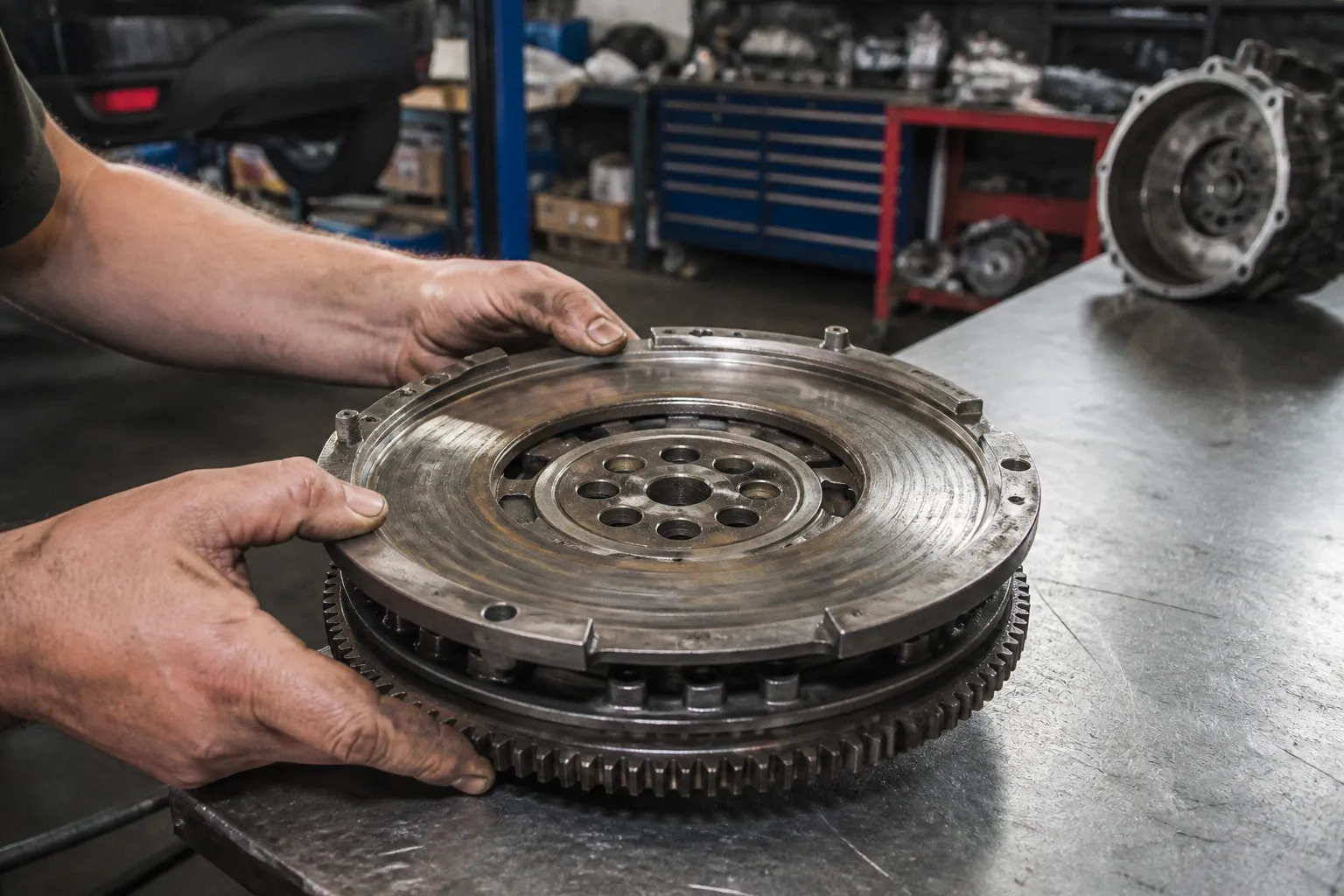
A dual-mass flywheel contains two rotating masses. The first is connected to the crankshaft. The second transfers torque to the clutch. Arc springs and friction dampers are positioned between them. Their function is to absorb torsional oscillation before it reaches the clutch disc, gearbox gears, and transmission shafts.
A four-cylinder diesel engine produces strong low-speed torque pulses. A small-displacement turbocharged petrol engine can produce the same problem through high cylinder pressure at low engine speed. Without adequate damping, each combustion event is transmitted as a sharp torsional input. The gearbox then receives a sequence of irregular torque reversals rather than a smooth rotational load.
The DMF is not a simple flat friction surface. Its internal parts operate as a calibrated mechanical system:
- The arc springs control relative rotational movement between the two flywheel masses.
- Friction dampers control the rate and resistance of that movement.
- The axial bearing supports controlled relative motion between the masses.
- Internal grease provides lubrication and assists damping.
- The friction surface transfers engine torque to the clutch disc.
Wear in one section changes the behaviour of the entire assembly. Spring fatigue can increase angular movement. Friction-damper wear can reduce resistance to oscillation. Bearing damage can produce noise and roughness. Grease leakage can remove lubrication and leave contaminated surfaces. Thermal damage can alter the friction surface and weaken adjacent components.
The result is not always clutch slip. A DMF may be mechanically damaged while the clutch disc still holds torque. It may also produce vibration and noise before any obvious loss of drive occurs.
A DMF is not diagnosed by one noise. It is diagnosed by the noise, the operating condition, the clutch-pedal response, and the exclusion of external causes.
Dual mass flywheel failure symptoms diagnostic
The most useful first test is a controlled idle comparison. The engine must be brought to operating temperature. The vehicle must be secured. The transmission must be in neutral. The parking brake must be applied. No body part is placed near rotating components.
The following sequence separates the main symptom groups:
1. Listen at idle with the clutch pedal released.
A metallic rattle or knocking noise from the gearbox area is relevant. The noise should be observed at stable idle speed, not during a momentary start-up fluctuation.
2. Fully depress the clutch pedal.
If the noise disappears immediately, the DMF remains a primary suspect. Relative movement between the engine side and transmission side has been altered by clutch disengagement.
3. Release the pedal without changing engine speed.
If the rattle returns, the result is repeatable. If the sound changes randomly, external components must be inspected before the flywheel is condemned.
4. Observe vibration at idle and during low-speed take-up.
Excessive DMF wear can transmit low-frequency vibration through the steering wheel, seat, floorboard, and clutch pedal. The strongest vibration is often felt at idle or during low-rpm engagement.
5. Monitor starting and shutdown.
A pronounced shudder during engine start or engine stop indicates that torsional movement is not being controlled correctly. The starter motor, engine mounts, fuel system, and crankshaft position signal must still be considered.
6. Test torque transfer under load.
If engine speed rises without a corresponding increase in vehicle speed, clutch slip is present. If slip occurs without the smell of burning clutch facing, internal DMF components may be slipping rather than the friction disc itself.
The symptom combination is more valuable than any single observation. A rattle that disappears with the clutch depressed is a strong directional result. It is not sufficient if the same vehicle has a damaged transmission mount or a loose exhaust shield.
Separating DMF noise from related faults
A release bearing commonly changes noise when the clutch pedal is loaded. That behaviour does not identify the DMF. A release bearing can become noisy when the pedal is depressed, while a DMF rattle often disappears at the same moment. The distinction is based on the exact transition and the sound source.
The gearbox input shaft and its bearings may generate whine or rumble. Gear oil level and condition must be checked according to the manufacturer’s procedure. A transmission fault can coexist with a failing DMF. Replacing the flywheel will not repair damaged gearbox bearings.
Engine mounts can transmit vibration through the body. A failed mount may create a heavy knock during start-up, shutdown, or abrupt throttle application. The mount should be inspected for separation, collapse, fluid leakage, and excessive movement.
The starter ring gear must be examined if the noise is concentrated during cranking. Damaged teeth can produce a harsh engagement sound. This is not the same fault as a DMF rattle at steady idle.
Exhaust shields and brackets must be checked manually when the system is cold. Thin metallic components can imitate a flywheel rattle. They often respond to engine movement or vibration. Their noise may be altered by touching the shield with a suitable tool, but contact with hot or moving components is prohibited.
The diagnostic logic is straightforward:
- If the noise occurs only during cranking, then inspect the starter and ring gear first.
- If the noise occurs at idle and changes when the clutch is depressed, then inspect the DMF and release system.
- If vibration is present with no change in clutch-pedal response, then inspect mounts, engine operation, and driveline alignment.
- If the engine speed rises without vehicle acceleration, then inspect clutch torque capacity and the DMF for internal slip.
- If a scan tool shows no fault code, then no conclusion about DMF condition is permitted.
How to test a dual mass flywheel without guessing
A roadside test can identify a pattern. It cannot measure internal spring condition. A proper diagnosis is completed in stages.
Stage one: reproduce the operating condition
The engine temperature, idle speed, clutch position, and transmission state must be recorded. The test should be repeated with electrical loads switched off and then on if engine idle quality is questionable. Alternator load can alter idle smoothness. It does not directly diagnose the flywheel.
The sound should be localized from the engine bay and gearbox housing. A mechanic’s stethoscope may assist, but the probe must not contact belts, pulleys, cooling fans, or other rotating components. A recording can document the change between pedal released and pedal fully depressed. It is useful evidence, not a measurement of internal clearance.
Low-speed road testing should be performed in a high gear only when safe and permitted. The engine must not be forced below its stable operating range under heavy throttle. Lugging creates torsional vibration and can accelerate damage. It also creates a false impression of flywheel failure by producing abnormal drivetrain loading.
The following observations are relevant:
| Observation | Diagnostic value | Next action |
|---|---|---|
| Metallic rattle at idle with pedal released | Strong DMF suspicion | Repeat with pedal fully depressed |
| Rattle disappears when pedal is fully depressed | Confirms a clutch-state dependency | Inspect DMF, release system, mounts, and gearbox |
| Vibration through floor and pedal at low rpm | Possible spring, damper, or mount fault | Compare with engine-mount movement and engine smoothness |
| Shudder during start or shutdown | Possible loss of torsional control | Inspect DMF and starter system |
| Slip with burning friction smell | Clutch friction material is a primary suspect | Inspect clutch disc, pressure plate, and flywheel surface |
| Slip without burning friction smell | Internal DMF slip is possible | Remove transmission for direct inspection |
| No OBD-II code | Expected for a mechanical DMF fault | Continue mechanical diagnosis |
Stage two: remove the transmission
The DMF cannot be reliably approved or rejected from the driver’s seat. If the symptom pattern is strong, the transmission is removed. The clutch assembly is then inspected before a replacement decision is made.
The inspection must include the friction surface, spring response, relative movement between the masses, axial movement, bearing condition, and evidence of grease escape. Exact angular play and axial movement limits are not universal. They vary by flywheel design, engine application, manufacturer, and service procedure.
There is no valid generic dual mass flywheel play tolerance that can be applied to every import vehicle. A measured value has meaning only when compared with the specification for that exact flywheel. The number of visible teeth, the diameter of the assembly, and the engine displacement do not establish a permissible limit.
If the manufacturer’s procedure specifies a direction of rotation for the play check, that direction must be followed. If a locking tool or special gauge is required, improvised leverage can damage the assembly or produce a false reading. The flywheel is not evaluated by forcing it until movement is felt and then assigning an arbitrary number.
A direct measurement should answer four questions:
1. How much relative rotational movement is present between the two masses?
2. Is spring resistance smooth across the movement?
3. Is axial movement within the application-specific limit?
4. Are noise, roughness, binding, grease loss, or impact marks present?
If rotational movement is smooth and within the manufacturer’s limit, the DMF is not automatically serviceable. Visible cracks, thermal damage, grease leakage, or rough bearing movement can justify replacement. If movement exceeds the specified limit, the assembly is rejected even if the friction surface appears clean.
Bench inspection: thermal damage and grease leakage
The flywheel must be inspected after removal and cleaning. Contamination can hide damage. Cleaning must not dissolve evidence that is needed for diagnosis or spread grease across the friction surface.
Thermal damage is visible in several forms:
- Discoloration of the friction surface.
- Fine surface micro-fissures.
- Yellowing around the lower axial bearing region.
- Burnt grease residue.
- Darkened or uneven contact areas.
- Localized heat marks rather than uniform surface colour.
These marks indicate heat exposure and frictional stress. They do not establish the precise temperature reached. A surface that appears visually acceptable may still have internal spring or bearing damage.
Grease leakage is a critical finding. The DMF depends on internal lubrication. Burnt grease residues indicate that the internal environment has been exposed to excessive heat or that the sealing system has failed. The presence of grease on or near the friction surface can also compromise clutch engagement.
The assembly must not be treated like a traditional single-mass flywheel. A conventional flywheel may sometimes be machined according to a defined resurfacing procedure. A DMF contains calibrated internal components. It is not economically or technically restored by ordinary machining of the friction surface. Resurfacing does not renew fatigued arc springs, worn friction dampers, damaged bearings, or lost grease.
The same applies to visible play. External movement is not repaired by tightening a fastener. The internal elements are not service-adjustable. Once the assembly has exceeded the permitted condition, replacement is the corrective action.
The crankshaft rear seal and transmission input seal should be inspected while access is available. Oil contamination can damage a new clutch and obscure the original cause of slip. Any leak must be corrected before the replacement assembly is installed. A dry flywheel with a clean friction surface is required.
Why the clutch is normally replaced with the flywheel
Replacing a DMF requires transmission removal. The labour overlap with clutch replacement is substantial. Installing a new clutch while leaving a worn flywheel in service transfers the old risk into the new repair.
The clutch kit normally includes the friction disc and pressure plate. A release bearing or concentric slave cylinder may be included depending on the application. The exact contents must be confirmed by part number. A hydraulic release component is not universal across import vehicles.
The combined replacement is recommended for mechanical reasons, not only for cost control:
- The old DMF may have uneven heat damage that compromises the new friction disc.
- Existing internal play can create new clutch judder after installation.
- A worn pressure plate may not clamp consistently against the replacement flywheel.
- A used release bearing can fail after the transmission has been reinstalled.
- A second transmission removal creates duplicate labour and increases installation risk.
The clutch disc must be installed in the correct orientation. The pressure plate must be tightened in the specified sequence and to the specified torque. Flywheel bolts are commonly treated as application-specific fasteners. If the service procedure requires new bolts, reused bolts are not acceptable.
The crankshaft flange and flywheel mounting faces must be clean. No abrasive debris is permitted between the mating surfaces. Runout and fastener seating must be controlled according to the vehicle procedure. A flywheel installed against contamination can create vibration that resembles the original fault.
After installation, the hydraulic system is bled when required. Clutch pedal travel is checked. Engagement height is recorded. The transmission is not forced into gear to compensate for incomplete release. If gears remain difficult to select, the release system and clutch alignment must be tested before the vehicle is returned.
Single-mass flywheel conversion: mechanical trade-offs
A single-mass flywheel conversion removes the internal damping mechanism from the flywheel. The conversion may use a rigid flywheel with a sprung clutch disc, depending on the kit. The result is a different torsional system. It is not a direct durability upgrade in every application.
The potential advantage is mechanical simplicity. There are fewer internal flywheel elements to wear. The assembly may tolerate a different operating environment. The potential disadvantages are transmitted vibration, gear rattle, harsher engagement, and greater torsional loading within the gearbox and driveline.
The outcome depends on the engine’s torque curve, idle strategy, gearbox design, vehicle mass, and calibration. A diesel with high low-rpm torque is not equivalent to a naturally aspirated petrol engine. A conversion that operates acceptably in one application can create persistent noise or driveline harshness in another.
The main trade-offs are:
| Parameter | Dual-mass flywheel | Single-mass conversion |
|---|---|---|
| Torsional damping | Provided by internal springs and friction dampers | Reduced or transferred to the clutch disc |
| Low-rpm refinement | Generally better when the system is healthy | More vibration and gear rattle may be transmitted |
| Internal wear points | Springs, dampers, bearing, grease, and friction surface | Fewer flywheel internals |
| Clutch engagement | More controlled by the damping system | Can be sharper or less tolerant of poor technique |
| Gearbox loading | Torsional pulses are damped before transmission | More pulse energy can reach the gearbox |
| Compatibility | Designed for the original engine and transmission package | Must be matched to the exact application |
| Legal and emissions status | Original equipment configuration | Conversion legality and compatibility are region-specific |
The decision cannot be made from the phrase single mass flywheel conversion pros and cons alone. The exact kit, clutch disc design, gearbox, engine calibration, and regional requirements must be identified. Compatibility must not be inferred from physical fitment. A component can bolt to the crankshaft and still produce unacceptable torsional behaviour.
If a manufacturer-approved or application-specific conversion is available, its design data should be reviewed. If no defined compatibility information exists, the original DMF configuration remains the controlled baseline.
Repair cost and replacement specification
A typical European DMF replacement range is approximately €900 to €1,800. The figure depends on the vehicle, parts selection, labour rate, access, clutch configuration, and whether additional seals or hydraulic components are replaced. It is not a fixed price for every import vehicle.
A quote should identify the actual components. The phrase flywheel replacement is insufficient. The repair scope should state whether it includes:
- Dual-mass flywheel.
- Clutch friction disc.
- Pressure plate.
- Release bearing or concentric slave cylinder.
- Flywheel bolts.
- Crankshaft or transmission seals where leakage is found.
- Transmission fluid lost during removal.
- Hydraulic bleeding and post-repair adjustment.
The replacement flywheel must match the engine code, transmission code, production range, and original design specification. Visual similarity is not enough. Mass distribution, spring calibration, friction geometry, starter ring gear, and axial dimensions are application-specific.
A new clutch installed on a damaged or incorrectly specified flywheel is not a completed repair. The vehicle may move under light load and still exhibit judder, noise, slip, or abnormal gearbox rattle.
Final verification parameters
Repair verification is completed from the original symptom forward. The same operating conditions are reproduced after installation.
The baseline is:
- Engine at normal operating temperature.
- Transmission in neutral.
- Stable idle speed according to the vehicle specification.
- No metallic rattle from the gearbox area with the clutch released.
- No abrupt change to an abnormal noise when the clutch is depressed.
- No excessive vibration through the steering wheel, seat, floorboard, or clutch pedal.
- No shudder beyond the vehicle’s normal behaviour during start and shutdown.
- No engine-speed flare without corresponding vehicle acceleration.
- Correct clutch engagement and full disengagement.
- No fluid leakage at the crankshaft rear seal, transmission input seal, or hydraulic system.
- Correct flywheel and clutch fastener torque.
- No new gearbox noise during low-speed and loaded operation.
If the original rattle remains after replacement, the DMF was not the only fault or the installation is incorrect. The release bearing, transmission input bearing, engine mounts, starter ring gear, exhaust shields, and gearbox oil condition must be revisited.
The decisive parameter is not the absence of an OBD-II code. That absence is expected. The decisive result is mechanical: controlled idle noise is eliminated, clutch-state behaviour is normal, vibration is reduced to the vehicle baseline, torque transfer is stable, and the installed parts meet the exact application specification.