Does a rebuilt turbocharger need professional balancing?
The Center Housing Rotating Assembly (CHRA) of an import turbocharger operates at rotational speeds that can range from roughly 30,000 RPM in larger-displacement units to more than 100,000 RPM in…
Merritt Vane·Updated: August 15, 2026·15 min read
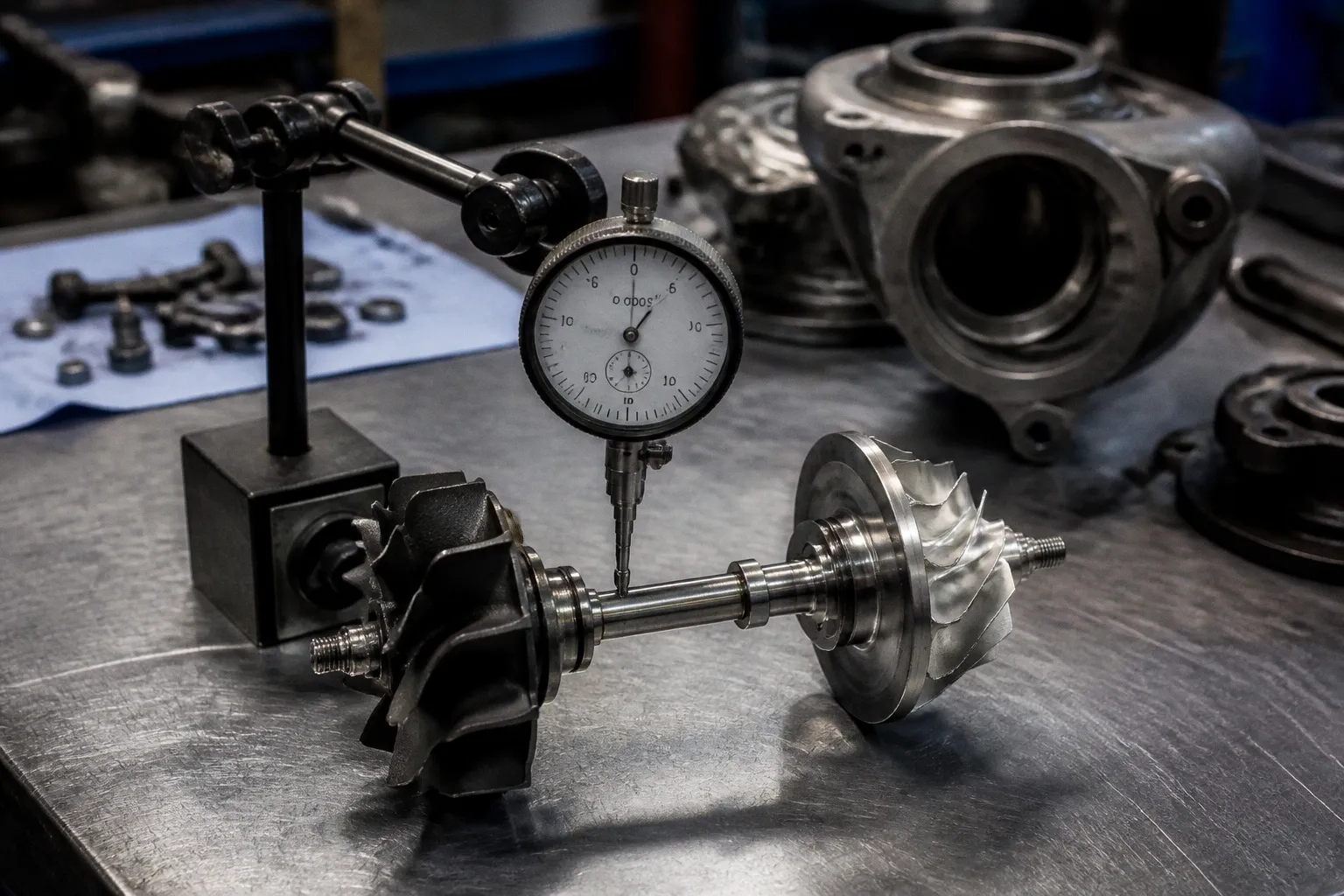
The Center Housing Rotating Assembly (CHRA) of an import turbocharger operates at rotational speeds that can range from roughly 30,000 RPM in larger-displacement units to more than 100,000 RPM in smaller-frame turbos used on many four-cylinder European and Asian platforms. At those speeds, even a small residual imbalance can create a vibration problem that the journal bearing, oil film, and housing were never intended to manage indefinitely.
That is why the question of turbo rebuild balancing necessity cannot be answered by looking at the replacement parts in isolation. A wheel may have been balanced before it was sold. A technician may have marked the shaft and compressor wheel before disassembly. Neither fact proves that the completed CHRA is dynamically balanced after reassembly.
The usual DIY argument is understandable: if the original parts were indexed, and the replacement wheel was advertised as pre-balanced, putting everything back in the same orientation should restore the factory condition. That approach can work as a reference during disassembly. It does not replace balancing the finished rotating assembly.
The Myth of Indexing and Pre-Balanced Components
A turbocharger rotor is not a single part. It is an assembly made up of the turbine wheel and shaft, thrust components, compressor wheel, and nose nut, all clamped together with specific seating surfaces, clearances, and torque requirements. Each part contributes its own manufacturing tolerance and residual mass variation.
A replacement compressor wheel can be correctly balanced as an individual component and still alter the balance of the completed rotor. The reason is not necessarily a manufacturing defect. The new wheel may have a slightly different mass distribution from the part it replaces, even when both parts meet their individual specifications. The bore, hub face, blade geometry, and the location of previous material removal all affect how the wheel behaves when it is installed on a particular shaft.
The same applies to a replacement turbine shaft and wheel assembly. The balance state of the original rotor was determined by the relationship between its specific components. An index mark records that relationship. It does not create a universal alignment position that will automatically work with a different wheel, shaft, thrust collar, or nut.
Indexing is still useful. It helps preserve orientation during inspection and can reduce unnecessary variation when the same serviceable parts are being reassembled. But it should be treated as an assembly aid, not as proof that the rebuild is balanced.
The phrase “pre-balanced” also needs to be read carefully. In parts catalogues, it may refer to an individual wheel, a shaft-and-wheel assembly, or a cartridge that has already been balanced by the supplier. Those are not interchangeable descriptions. The rebuilder needs to know what was balanced, in what configuration, and whether the completed CHRA was tested after the final components were torqued together.
A low-speed bench fixture has a similar limitation. It can help identify a static offset or reveal obvious assembly problems, but it does not reproduce the complete operating environment of a turbocharger. A high-speed rotor can respond differently as it passes through its operating range. Bearing clearances, oil-film behavior, housing stiffness, thermal expansion, and aerodynamic loading all influence the vibration signature.
A rebuilt turbocharger is not four balanced parts screwed together; it is one rotating assembly whose balance state must be verified as a unit.
Understanding Cumulative Stack-Up Errors in Turbo Assemblies
Tolerance stack-up is the practical reason that diy turbo rebuild balancing is more complicated than balancing a loose wheel on a simple fixture.
The shaft has its own runout and concentricity characteristics. The compressor wheel has a bore and hub face that must seat correctly on the shaft. The turbine wheel and shaft may have their own relationship, while the thrust collar and nut introduce additional seating surfaces. When the assembly is clamped, these individual conditions combine into one rotating system.
The errors do not simply disappear because each component was manufactured carefully. In some assemblies, the deviations may partly oppose one another. In others, they may reinforce one another. The final result depends on the actual parts, their orientation, the condition of the seating faces, and the torque applied during assembly.
A useful way to think about the problem is to separate three questions:
1. Is each component within its own specification?
This covers wheel condition, shaft runout, bore dimensions, thread condition, and visible damage.
2. Are the components assembled correctly?
The correct thrust parts, spacers, washers, and nut must be installed in the correct order. The mating faces must be clean and free from burrs or debris.
3. Does the completed rotor meet its dynamic balance requirement?
This can only be established by testing the assembled unit, not by assuming that the first two conditions guarantee the third.
A small seating error can matter even when the underlying components are good. Dirt between a wheel and a hub, a damaged locating face, incorrect torque, or a nut that does not clamp the stack evenly can change the rotor’s behavior. A used shaft can also be unsuitable despite appearing straight by eye. The bearing journals may be worn, the thread may have been stretched or damaged, and previous overheating may have altered the material.
For that reason, a rebuild kit does not answer the question, do you need to balance a turbo rebuild kit? The kit may contain accurately manufactured parts, but it does not remove the need to verify the assembled CHRA. The relevant object is the finished rotor in its service configuration.
The effect of imbalance also depends on the turbocharger design. A large-frame unit, a small high-speed unit, a journal-bearing cartridge, and a ball-bearing cartridge do not all respond in exactly the same way. Their bearing systems, clearances, shaft dimensions, and operating ranges differ. A general claim that one numerical tolerance or one balancing procedure applies identically to every turbocharger is not reliable.
What a careful rebuild inspection includes
Before balancing, a professional rebuilder will normally establish whether the parts are worth assembling in the first place. The inspection may include:
- checking shaft runout with a dial indicator or dedicated measuring fixture;
- inspecting the bearing journals for scoring, discoloration, or signs of oil starvation;
- checking the compressor wheel and turbine wheel for bent blades, cracks, impact marks, or contact damage;
- examining the bore and hub faces for burrs, raised metal, and contamination;
- confirming that the thrust components match the turbocharger application;
- measuring relevant clearances against the manufacturer’s or rebuilder’s specifications;
- checking that the bearing housing and seal areas have not been distorted by overheating;
- confirming that the oil passages are open and that the replacement parts are correct for the cartridge.
Balancing cannot repair a shaft with unacceptable runout, a cracked wheel, a worn bearing housing, or a damaged thrust system. It is a verification and correction process for a serviceable assembly, not a way to make unsuitable parts usable.
The Mechanics of VSR Balancing: Testing at Operational RPM
VSR balancing—commonly expanded as Vibration Sorting Rig balancing—is used to evaluate the dynamic behavior of a fully assembled turbocharger cartridge. The important distinction is that the CHRA is tested as a complete unit, at high speed, with lubrication supplied to the bearings.
The assembled cartridge is mounted in a fixture and connected to a pressurized oil supply. The rig then accelerates the rotor through an appropriate speed range while sensors monitor the vibration response of the housing. The test is designed to show how the assembly behaves as it approaches and passes through the speed ranges relevant to its application.
This is different from spinning a loose wheel or a dry rotor on a low-speed stand. The oil film is part of the bearing system, so the test conditions need to account for its influence. The housing, bearing arrangement, shaft, thrust components, and wheel assembly all contribute to the measured response.
During the test, the equipment identifies the amplitude and location of the vibration. The rebuilder can then remove a controlled amount of material from an appropriate balance plane, or use another approved correction method, depending on the turbocharger design. The unit is tested again after correction. The objective is not simply to produce a visually smooth spin; it is to bring the completed CHRA within the applicable vibration limit for that frame and configuration.
| Parameter | What the test addresses | Why it matters |
|---|---|---|
| Test speed | The relevant operating range for the turbocharger | Imbalance can become more apparent at higher speed or near a resonance |
| Lubrication | Pressurized oil supplied to the bearing system | Bearing behavior changes when the oil film is active |
| Assembly state | Fully assembled and torqued CHRA | The test includes the actual component stack-up |
| Vibration response | Housing vibration measured during the speed sweep | The response shows whether the rotor behaves acceptably as a unit |
| Correction | Controlled material removal or another approved adjustment | The correction targets the measured imbalance rather than an assumed one |
| Verification | A second test after correction | The rebuilder confirms that the change produced the intended result |
The exact test limits are not universal. They depend on the equipment, turbocharger family, bearing design, frame size, and service specification. That is one reason a generic DIY turbo rebuild balancing setup can be misleading. A fixture may tell you that a part rotates, but it may not provide the measurement quality, speed range, oil supply, or correction procedure needed for a professional rebuild.
A low-speed balance can still have a place in the workflow. It may help identify a gross error before the cartridge is sent to a high-speed rig. It can also be useful when checking a component during manufacturing or inspection. It should not be presented as an equivalent substitute for VSR testing of the finished CHRA.
Precision Tolerances: Why 0.0003 Inches Matters for Shaft Runout
Shaft runout is one of the first measurements that determines whether a used turbocharger shaft should be reused. The commonly referenced service limit of approximately 0.0003 inches—around eight microns—illustrates the scale involved. The number is small enough that visual inspection is not an adequate method of approval.
Runout is measured with the shaft supported correctly and an indicator positioned at a defined point. The procedure matters. Poor support, dirt on a precision center, a damaged measuring tip, or an incorrect measuring location can produce a reading that does not represent the shaft’s actual condition.
The measurement also needs to be interpreted in context. A shaft that is just within a published limit may still deserve closer attention when paired with other marginal components. The condition of the bearing journals, the balance history of the turbocharger, and evidence of overheating or wheel contact all influence the reuse decision.
A shaft can be damaged without being visibly bent. Common warning signs include:
- blue or darkened areas associated with excessive heat;
- scoring or polishing on the bearing journals;
- wear near the thrust area;
- damaged threads or a distorted nut seat;
- impact marks from previous wheel contact;
- evidence that the shaft has spun in a worn bearing or has suffered oil starvation.
New bearings and wheels cannot compensate for a shaft that is outside the required runout specification. Nor can a balance machine turn a damaged journal into a sound bearing surface. If the foundation of the rotor is not serviceable, the correct repair is to replace the affected component or use a qualified remanufacturing process—not to balance around the defect.
The same caution applies to the bearing housing. Its bore, oil passages, thrust surfaces, and seal areas must be inspected. A balanced rotor installed into a housing with excessive wear can still develop poor oil control, shaft movement, or contact with the housings. Balancing is necessary for the rotating assembly, but it is only one part of a complete rebuild.
Consequences of Imbalance: From Oil Film Breakdown to Failure
An unbalanced turbocharger does not always announce itself with an immediate, dramatic noise. The early symptoms can be subtle and may overlap with other faults in the intake, exhaust, lubrication, or engine-management systems.
Possible unbalanced turbocharger symptoms include:
- a new high-pitched whine that changes with engine speed;
- vibration or a rougher sound that was not present before the rebuild;
- compressor or turbine wheel contact marks;
- increasing shaft movement during inspection;
- oil appearing in the compressor inlet, charge system, or exhaust side;
- reduced boost or inconsistent boost control;
- smoke under conditions where the engine previously ran cleanly;
- repeated bearing or seal damage after an otherwise correct installation.
None of these symptoms proves that imbalance is the cause. A boost leak, restricted oil drain, contaminated oil supply, actuator fault, foreign-object damage, excessive crankcase pressure, or installation error can produce similar results. Diagnosis should therefore include the complete system rather than treating every turbo noise as a balancing failure.
When imbalance is present, the rotating shaft applies a changing load to the bearing system. If that load exceeds what the oil film and bearing clearances can accommodate, the shaft may move farther from its intended centerline. The result can be intermittent contact, accelerated bearing wear, or changes in the way oil is controlled at the seals.
The progression is not identical in every turbocharger. Some assemblies may show noise and shaft movement before any significant oil leakage. Others may suffer seal problems or wheel contact relatively quickly if the rotor has substantial damage or the bearing system is already compromised. Operating conditions also matter: oil quality, oil pressure, engine speed, exhaust temperature, and the duration of the fault all influence the outcome.
How damage can spread beyond the turbocharger
Oil leakage from a failed turbocharger can affect other components, but the consequences are component-specific rather than automatic. Oil in the compressor side may contaminate the intake piping, intercooler, and sensors. Depending on the engine and the amount of oil present, it may require cleaning or replacement of affected parts before the vehicle is returned to service.
Oil entering the exhaust side can contribute to smoke, deposits, or damage to emissions-control components. A catalytic converter or particulate filter may be affected if it is exposed to a sustained amount of oil or debris, but the result depends on the engine, the type of failure, the quantity involved, and how long the vehicle was operated afterward.
A serious rotor failure can also send metal fragments into the intake or exhaust path. The risk to the engine depends on where the fragments travel and whether the compressor or turbine wheel has broken apart. On some vehicles, foreign material may remain in the intercooler or charge pipes; on others, it may reach the engine. That possibility is why a failed turbocharger should not simply be replaced without inspecting the connected systems.
The appropriate repair may range from cleaning the charge-air system and replacing contaminated components to repairing additional engine or emissions-system damage. It is not accurate to say that every unbalanced turbocharger automatically requires an engine rebuild or replacement. It is equally unwise to assume that the turbo is the only component that can be affected.
Imbalance is a process, not a single noise: the correct response is to find its source before wear, oil contamination, or wheel contact creates a second repair problem.
When DIY Rebuilding Stops Being Practical
A careful DIY mechanic can disassemble a turbocharger, document the original configuration, inspect the parts, and prepare the cartridge for rebuilding. That work has value. It can prevent contamination, identify obvious damage, and make the final assembly more predictable.
The boundary is the measurement and correction of the finished high-speed rotor. Most home workshops do not have a VSR rig capable of supplying pressurized oil, sweeping the required speed range, recording vibration accurately, and applying the correct correction procedure for the specific turbocharger. Buying a kit advertised as pre-balanced does not remove that limitation.
A sensible division of labor is often:
1. Remove and label the turbocharger carefully, keeping contamination out of the oil and air passages.
2. Record the orientation of the parts, without treating the marks as a substitute for final balancing.
3. Inspect the shaft, wheels, housing, bearings, thrust components, and seal areas.
4. Replace parts that fail inspection rather than attempting to balance around damage.
5. Send the assembled CHRA—or the parts, depending on the rebuilder’s process—to a specialist that can perform high-speed balancing.
6. Reinstall the turbocharger only after checking oil feed and drain condition, intake cleanliness, exhaust restrictions, and the cause of the original failure.
The specialist should be able to state what was balanced and provide a test result or service record appropriate to the unit. A statement that the wheels were balanced individually is not the same as confirmation that the completed CHRA passed a high-speed dynamic test.
Closing Position
For a turbocharger that has been opened and rebuilt, professional balancing of the completed CHRA is the reliable answer. It remains necessary even when the replacement wheels are described as pre-balanced and even when the original indexing marks were preserved.
The relevant service is high-speed dynamic balancing under suitable lubrication, normally performed with VSR equipment and followed by verification after correction. Low-speed balancing and careful indexing can support the rebuild process, but they do not establish that the finished cartridge will behave correctly across its operating range.
The rest of the installation matters just as much. The oil feed must be clean and suitable, the drain must be unrestricted, the intake and charge-air system should be checked for debris and contamination, and the original cause of turbocharger failure should be addressed. A balanced rotor cannot compensate for oil starvation, excessive crankcase pressure, a blocked drain, a foreign object, or a control-system fault.
The cost and turnaround of specialist balancing are easier to justify when viewed as risk control rather than as an optional finishing step. A failure after installation may involve the turbocharger alone, or it may contaminate connected systems and require additional diagnosis and cleaning. The exact outcome varies, but the basic mechanical point does not: a turbo rebuild kit supplies parts; professional balancing verifies the assembly those parts become.