Modern Automotive Diagnostics: Solving the Flash Programming Bottleneck
The Specialty Equipment Market Association reports significant momentum in workshop tools, lifting solutions, and diagnostic equipment ahead of the 2026 SEMA Show.
Aldous Moorland·updated September 19, 2026
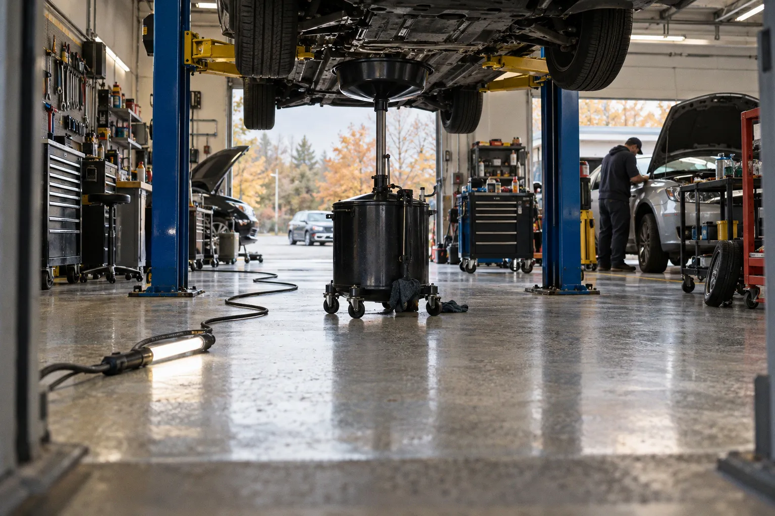
Demand escalates against vehicle electronic complexity, ADAS calibration requirements, and drivetrain installations across 296.5 million operating vehicles. The diagnostic baseline shifts. Throughput constraints relocate from mechanical assembly to software deployment.
Flash Programming Becomes the Bottleneck
Modern vehicle architectures replaced over 100 ECUs with a small number of high-performance computers (HPCs) and zone controllers. Each HPC executes multiple processor cores and operating systems in parallel, handling highly complex calculations. Software images now reach several tens of gigabytes. Flash time governs throughput in development and production alike.
Softing Automotive outlined the remediation pathway. The Multiflash Unit enables up to four HPCs to be programmed simultaneously via DoIP. When programming conventional ECUs via CAN, as many as eight software updates can be performed in parallel. The standalone workstation reduces flash time, increases flexibility, and improves software quality. Housing supports up to eight ECU connection ports. Four VIN|ING 2000 interfaces deliver performance across both CAN and DoIP communication. Flash sequences initiate from a test PC connected via Ethernet. Diagnostic applications include DTS.monaco for development and TDX for after-sales service.
Simulation and Pre-Prototype Validation
Flash processes require verification before physical ECUs arrive. Configurable diagnostic simulation solutions — Softing TCS.device — generate diagnostic communication either from trace data or from ODX data alone. This permits flashing workflows to be tested prior to ECU prototype availability. Process integrity is established before hardware lands on the bench. Tightly interconnected software components are validated against simulated module behavior rather than physical hardware cycles.
ADAS Calibration and Lifting Geometry
ADAS loads compound the diagnostic chain. Cameras, radar modules, and lidar sensors demand precise aiming against manufacturer-defined targets. Lifting solutions must accommodate sensor mounting geometry — height, wheel alignment access, and floor flatness. Drivetrain installations across hybrid, electric, and high-output combustion platforms require torque verification at exact baseline parameters. The aftermarket demand reflects these layered requirements.
Verification Parameters for Procurement
For shops absorbing the equipment surge: confirm DoIP and Ethernet capability before purchase. Verify CAN channel count against anticipated parallel ECU flash loads. Cross-check lifting height and load rating against ADAS calibration target placement. Protocol bandwidth must match operational throughput, not advertised specification. The 296.5-million-vehicle baseline defines the addressable demand. Equipment selection should anchor to protocol, not to feature lists.