Uneven brake pad wear: diagnostic guide and fixes
An inner brake pad wearing faster than the outer pad is not, by itself, a failed caliper. On a single-piston floating caliper, the piston acts directly on the inner pad. A wear difference of approximately 2 mm can occur during normal operation.
Aldous Moorland·Updated: August 17, 2026·14 min read
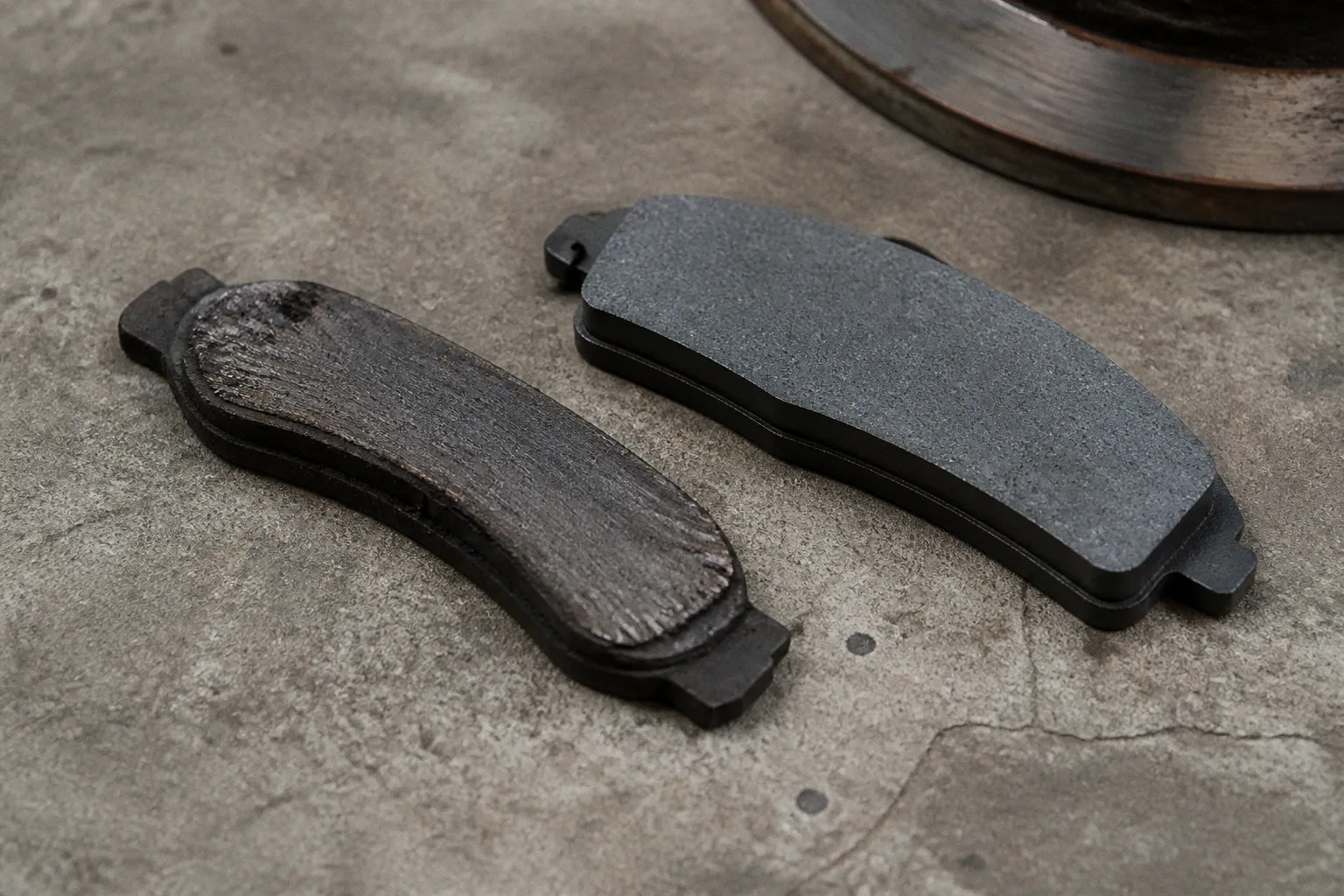
Beyond that range, or when the wear is accompanied by heat, pull, tapering, or rotor scoring, the brake assembly requires diagnosis before new pads are installed.
The correct task is not pad replacement. It is identification of the restriction. A seized slide pin, a sticking piston, corroded pad hardware, a damaged boot, a twisted flex hose, or incorrect component geometry can produce similar symptoms. The wear pattern separates these faults.
The caliper is a mechanical system with two release paths
A floating caliper must move laterally on its guide pins. The piston pushes the inner pad toward the rotor. Reaction force pulls the caliper body across the pins, bringing the outer pad into contact with the opposite rotor face.
Release requires two actions:
1. Hydraulic pressure must fall after the brake pedal is released.
2. The piston seal must retract the piston enough to create running clearance.
3. The caliper body must slide freely on its guide pins.
4. Both pads must move without binding in the bracket.
A defect in any one of these paths leaves friction material in contact with the rotor.
The system can be represented through strict diagnostic gates:
- If the inner pad is substantially thinner than the outer pad, piston retraction, hydraulic restriction, or caliper sliding resistance is suspected.
- If the outer pad is substantially thinner than the inner pad, guide-pin movement, pad-ear binding, or caliper-body movement is suspected.
- If the pad is wedge-shaped, installation geometry or hardware retention is suspected.
- If both pads are worn evenly but the rotor is damaged, the cause may be normal wear combined with a separate rotor or friction-material problem.
- If the same wheel becomes markedly hotter than its opposite side, dragging contact is present until proven otherwise.
New pads cannot correct a caliper that is still applying force after the pedal has been released.
Read the wear pattern before removing parts
Pad thickness must be measured at several points. A visual inspection through the wheel is insufficient. The friction material can be tapered, cracked, or separated from the backing plate while appearing acceptable from one angle.
The following patterns have distinct implications.
| Wear pattern | Most likely area of failure | Diagnostic direction |
|---|---|---|
| Inner pad thinner than outer pad | Piston, piston seal, hydraulic restriction, or limited caliper movement | Check piston retraction, hose condition, and caliper sliding resistance |
| Outer pad thinner than inner pad | Seized guide pin, corroded pad ears, or caliper body unable to center | Remove and inspect both guide pins and bracket contact surfaces |
| Horizontal or vertical taper | Pad ears, retention hardware, bracket distortion, or incorrect installation | Check whether the pad is supported evenly and seated squarely |
| Friction material overhangs the rotor edge | Incorrect pad or rotor dimensions, excessive bracket wear, or incorrect component combination | Confirm part numbers and friction-surface alignment |
| Both pads worn similarly, with rotor scoring | Contaminated or damaged friction surfaces, rotor runout, or normal wear with a separate defect | Inspect rotor and pad surface condition |
| One wheel heavily worn with heat discoloration | Caliper drag or hydraulic pressure not releasing | Compare wheel temperature and isolate mechanical versus hydraulic causes |
A small inner-versus-outer difference on a single-piston floating caliper is expected. The reference value is approximately 2 mm, not zero. The wear difference becomes diagnostic when it is clearly larger, increases rapidly, or is associated with other symptoms.
Inner pad wearing faster
An inner pad that is substantially thinner is commonly associated with a piston that does not retract. The piston may be corroded. The seal may be damaged. A twisted or internally restricted brake hose may retain pressure at the caliper. A kinked brake line can produce a similar hydraulic effect.
The diagnostic sequence is conditional:
1. If the inner pad is thinner and the caliper body slides freely, inspect piston movement and hydraulic release.
2. If the piston cannot be pressed back with the correct service method, inspect the piston, dust boot, and seal.
3. If pressure remains in the caliper after the pedal is released, isolate the hose and line condition before replacing the caliper.
4. If opening the hydraulic circuit changes the piston behavior, hydraulic restriction is indicated. Fluid handling and bleeding are then required.
5. If piston movement is normal and no pressure is retained, return to the caliper guide pins and pad hardware.
The piston should not be forced into the bore with uncontrolled pressure. On vehicles equipped with an integrated parking-brake mechanism, the piston may require rotation or a dedicated wind-back procedure. The service design must be confirmed before compression is attempted.
Outer pad wearing faster
An outer pad that is thinner than the inner pad shifts attention toward the floating mechanism. The caliper body must move across the guide pins after the inner pad has contacted the rotor. If a pin is seized, the body can remain displaced. The outer pad may stay loaded against the rotor or fail to release cleanly.
Pad ears can create the same result. Rust expands under the abutment clips. The pad then becomes clamped in the bracket. It cannot move as the caliper changes position. The visible symptom is uneven wear, but the actual fault is contact resistance at the bracket.
The guide pins must be removed, not merely sprayed from the outside. Their surfaces are inspected for pitting, corrosion, scoring, and dry areas. The rubber boots are inspected for tears, distortion, and loss of seating. Contamination from water and dirt enters through damaged boots. The pin then corrodes inside the bore.
Only brake-compatible synthetic high-temperature grease should be used where the caliper manufacturer permits lubrication. Petroleum-based lubricant can swell rubber components. A swollen boot or bushing restricts pin movement and converts a lubrication service into a repeat failure.
Sticky caliper slider pins: the mechanical inspection
Guide-pin service is often treated as a minor cleaning operation. That is incorrect when uneven brake pad wear is already present. The pin, boot, bore, bracket, and pad abutments form one mechanical assembly. Each component must be examined.
The inspection proceeds as follows:
1. The caliper is removed from the bracket without allowing the flexible hose to carry its weight.
2. The guide pins are extracted and kept associated with their original positions if the design uses different pin shapes or bushings.
3. The boots are removed only with tools that will not cut or deform the sealing surfaces.
4. Old grease and contamination are removed from the pins and bores.
5. The pin surfaces are checked for rust pits, wear grooves, and discoloration.
6. The boot lips are checked for full engagement with the pin and bracket.
7. The pin is reassembled with compatible synthetic brake grease in the quantity specified by the service design.
8. The pin is moved by hand through its full travel. Resistance, binding, or spring-back that is not specified by the design is a fault.
9. Pad ears and bracket abutments are cleaned until the pad can move freely without excessive clearance.
10. The pad is installed with the correct clips, shims, and orientation.
A guide pin that appears clean but binds inside the boot remains defective. A new pin may be required. The bracket bore may also be damaged. Grease cannot restore a pitted surface or correct a distorted boot.
The pad must not be lubricated on its friction face. Grease must not contact the rotor. It must not be applied between the pad friction material and the backing plate unless the vehicle-specific service procedure explicitly uses an approved noise-control product at that interface. The friction surface must remain dry and uncontaminated.
Tapered wear and overlapping friction material
A tapered pad has different thickness at opposite ends or along its vertical axis. This is not normal bedding. It indicates that the pad has not remained square against the rotor.
The causes include:
- A pad ear binding in the bracket.
- A retaining clip installed incorrectly.
- A guide pin with limited travel.
- A damaged or twisted caliper bracket.
- A caliper that is not seated correctly.
- Incorrect pad geometry.
- Excessive wear at a caliper mounting point.
- A friction material block that is not correctly bonded to the backing plate.
A tapered pad must not be reused. The cause must be corrected before the replacement set is fitted. Otherwise, the new pad will begin with the same misalignment.
Overlapping wear occurs when the pad does not match the rotor’s friction surface. The friction material may extend beyond the outer diameter of the rotor, or an unworn lip may remain at the rotor edge. The condition can result from an incorrect pad, an incorrect rotor, or excessive wear in the mounting system.
Part-number confirmation is required. The front and rear systems may use visually similar components with different dimensions. Import vehicles can also have market-specific brake packages. A catalog match based only on engine size is insufficient when multiple rotor diameters or caliper configurations were offered.
Rotor contact must be aligned across the usable friction surface. If it is not, the pad and rotor combination is not ready for service.
Separating mechanical binding from hydraulic restriction
A caliper can drag for mechanical or hydraulic reasons. The symptoms overlap. The test must separate them.
Mechanical restriction is more likely when:
- A guide pin cannot be moved through its normal range.
- A pad is tight in the bracket.
- The caliper body does not center after installation.
- The piston retracts correctly, but the assembly remains difficult to move.
- The dust boot is torn and the piston surface shows corrosion.
- The drag remains after guide-pin and pad-hardware service.
Hydraulic restriction is more likely when:
- The wheel remains loaded after pedal release.
- Pressure is found at the caliper when the system should be relaxed.
- The condition changes when the hydraulic connection is carefully isolated under the approved service procedure.
- The flex hose is twisted, kinked, externally damaged, or incorrectly routed.
- The piston moves only after hydraulic pressure is relieved.
Brake hoses can deteriorate internally without obvious external damage. The inner lining can act as a one-way restriction. Pressure reaches the caliper under pedal force, but return flow is limited after release. The result resembles a seized piston.
No hydraulic line should be loosened casually. Brake fluid is corrosive to paint and absorbs moisture from the environment. If the hydraulic circuit is opened, the correct fluid must be used and the system must be bled according to the vehicle’s sequence. Air in the caliper produces a soft pedal. It does not correct mechanical drag.
A brake bleed can remove air and contaminated fluid. It cannot free a seized guide pin. It cannot repair a damaged piston seal. It cannot correct a pad that is clamped by rust under an abutment clip.
A bleed procedure addresses fluid and air. It does not address metal-to-metal binding.
Heat, pull, and rotor evidence
A dragging brake converts vehicle motion into heat. The affected wheel can produce an acrid odor, pull the vehicle to one side, reduce fuel economy, and show severe heat concentration at the brake assembly. Continued driving can damage the pad, rotor, seal, wheel bearing, and brake fluid.
Comparison is more reliable than an isolated impression. After a controlled drive that does not involve repeated heavy braking, wheel temperatures can be compared with an infrared thermometer. The opposite side is the reference. A large asymmetry indicates that further inspection is required. The precise acceptable temperature difference depends on vehicle design, ambient conditions, road load, and braking history. No universal threshold should be substituted for the manufacturer’s data.
The rotor provides secondary evidence:
- Blue or dark heat discoloration indicates overheating.
- Radial scoring indicates contaminated or damaged friction material.
- A pronounced outer lip indicates wear and may interfere with measurement.
- Cracks or severe surface damage require rotor replacement.
- Uneven transfer material can create vibration or inconsistent braking.
Rotor replacement alone is not a repair if the caliper remains loaded. New friction surfaces will be damaged by the same fault. Pad and rotor replacement must follow correction of the binding mechanism.
The friction surfaces should be kept in axle sets. Pads should not be replaced on one side only. If one wheel has experienced significant drag, the paired pads on the same axle must be evaluated for heat damage and contamination. Replacement decisions remain vehicle-specific, but friction material with glazing, oil, brake fluid, separation, or severe thermal damage is not restored by simple sanding.
A controlled repair sequence
The efficient repair sequence begins with measurement rather than parts selection.
1. Confirm the symptom
Measure inner and outer pad thickness on both sides of the axle. Record the difference. Inspect for tapering, cracking, edge overhang, and backing-plate separation. Note whether the rotor is scored or discolored.
If the difference is close to the normal approximately 2 mm variance for a single-piston floating caliper and no drag is present, the caliper is not automatically defective. If the difference is large or accompanied by heat, continue.
2. Check the wheel and rotor
Compare wheel temperatures after controlled operation. Inspect the rotor surface and outer lip. A hot wheel identifies a drag condition but does not identify the failed component.
If no heat asymmetry is present, focus on pad seating, hardware, rotor geometry, and installation history. If one side is hot, inspect release movement before installing parts.
3. Inspect the pads and bracket
Remove the pads. Check whether each pad slides freely in its installed position. Rust under abutment clips must be removed from the bracket contact areas. Hardware that is corroded, distorted, or permanently deformed must be replaced.
If a pad is difficult to remove or install, the bracket interface is already a suspect. The pad must not be forced into position.
4. Inspect guide pins
Remove both pins. Check the boots and bores. If a pin is pitted, bent, dry, or seized, replace the damaged components. Apply only compatible synthetic high-temperature brake grease where specified.
If both pins move correctly and the pads are free in the bracket, proceed to piston and hydraulic checks.
5. Check piston retraction
Use the approved tool and procedure for the caliper design. Observe whether the piston retracts smoothly. A piston with a torn boot, corrosion, or abnormal resistance requires caliper repair or replacement.
If the piston retracts normally but drag returns after pedal application, hydraulic restriction becomes more probable.
6. Check the hose and line
Inspect hose routing, twists, kinks, and external damage. Pressure-retention testing must be performed with the correct tools and procedure. If the hydraulic circuit is opened, bleeding is mandatory.
7. Verify geometry and installation
Confirm pad and rotor part numbers. Check caliper bracket condition and mounting surfaces. Verify that clips, shims, pins, and wear indicators are positioned correctly. Mounting fasteners are torqued to the vehicle-specific specification, not a generic value.
8. Bed the replacement components
After the fault is corrected, the replacement pads and rotors are bedded according to the manufacturer’s procedure. Repeated hard stops from arbitrary speeds are not a universal bedding method. The procedure depends on the friction material and vehicle.
The brake pedal must be firm before the vehicle is returned to service. Fluid leaks are not acceptable. The wheel must rotate with the expected unloaded resistance. The final road test must confirm straight-line braking, absence of abnormal odor, and no repeat temperature imbalance.
The parameters that verify the repair
A repair is complete only when the original condition has been removed and the mechanism has been checked.
The final baseline consists of:
- Inner and outer pad thickness recorded on both sides of the axle.
- No abnormal taper or friction-material overhang.
- Pads moving freely in their bracket contact points.
- Guide pins moving through their specified travel without seizure.
- Boots seated correctly and free of tears.
- Piston retracting by the vehicle-specific procedure.
- No evidence of retained hydraulic pressure.
- Rotor friction surfaces aligned with the pad material.
- Correct pad and rotor part numbers installed.
- No fluid leakage.
- Firm, consistent brake-pedal response after any required bleeding.
- No significant wheel-temperature asymmetry after a controlled road test.
- No vehicle pull, burning odor, or repeat drag.
Uneven brake pad wear is a wear pattern, not a diagnosis. The pattern identifies the path that has failed. Inner-pad wear directs inspection toward piston retraction and hydraulic release. Outer-pad wear directs inspection toward guide pins, pad ears, and bracket movement. Tapered wear directs inspection toward geometry and installation.
Once those logic gates are followed, the repair becomes finite. The correct baseline is not a new set of pads. It is free mechanical travel, released hydraulic pressure, aligned friction surfaces, and measured wear that remains consistent across the axle.