VVT Solenoids: How Oil Pressure Controls Valve Timing
A VVT fault can exist with correct electrical resistance, a functioning fuse, and acceptable engine oil pressure at the oil filter housing. The failure may still be hydraulic.
Aldous Moorland·Updated: August 13, 2026·17 min read
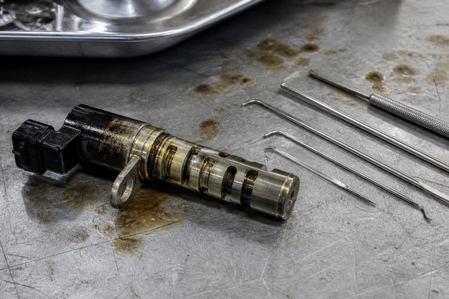
Variable valve timing depends on a narrow oil passage, a clean control screen, a responsive solenoid spool, and an actuator that can hold pressure without internal leakage.
The central error in many diagnoses is treating the VVT solenoid as an electrical switch. It is not. The engine control module commands a pulse-width-modulated valve. That valve meters pressurized engine oil into one side of a camshaft phaser. The phaser changes cam position relative to the crankshaft. If oil flow is restricted, delayed, aerated, contaminated, or discharged through a worn actuator, commanded timing and actual timing diverge.
That is the mechanism behind VVT solenoid oil pressure failure. The solenoid may receive the correct command. The camshaft may still remain outside its target position.
The hydraulic link: how oil pressure drives variable valve timing
A variable valve timing system has four operating elements:
1. The engine control module, which calculates the required camshaft angle.
2. The VVT solenoid, also called an oil control valve, which meters oil.
3. The camshaft phaser or actuator, which converts oil pressure into rotational movement.
4. The oil supply circuit, including galleries, filters, screens, seals, and the oil pump.
The camshaft phaser is fixed to the camshaft. Its outer housing is driven by the timing chain or belt. An internal rotor is connected to the camshaft. Oil pressure applied to different chambers moves the rotor relative to the housing. This changes the camshaft phase while the crankshaft continues to rotate.
The solenoid does not create hydraulic pressure. It redirects and regulates pressure already produced by the lubrication system.
That distinction determines the diagnostic path. If pressure is missing at the solenoid inlet, replacing the solenoid cannot correct the condition. If pressure is available but the solenoid does not meter it, the valve becomes the primary suspect. If metered pressure reaches the phaser but the camshaft does not move, actuator leakage, mechanical binding, or timing-chain displacement must be considered.
The control loop
The control system operates as a feedback loop:
- The engine control module commands a camshaft angle.
- The VVT solenoid is driven at a specified duty cycle.
- Oil is routed into an advance or retard chamber.
- The camshaft position sensor reports actual cam position.
- The module compares commanded and measured values.
- Solenoid duty cycle is revised.
A fault is produced when the measured result does not follow the command within the expected time and tolerance.
The module does not need to detect a completely failed solenoid. A slow response can be sufficient. If the camshaft reaches the target position after the permitted time, or overshoots the target, a fault may be stored even though the engine remains operational.
The VVT solenoid controls oil direction and volume. The actuator converts that controlled oil pressure into camshaft movement.
The system is therefore sensitive to more than absolute pressure. Flow rate, pressure retention, oil viscosity, air content, and internal clearance all affect response.
Oil pressure is not one measurement
A pressure reading taken at the engine oil gallery provides useful information. It does not prove that the VVT actuator is receiving usable pressure.
Oil pressure varies by location and operating condition. A pump may produce adequate pressure at the main gallery while a restricted passage prevents sufficient flow at the cylinder head. A worn phaser may receive oil but fail to retain it. A solenoid screen may be partially blocked and pass enough oil at idle to appear functional while starving the actuator during a commanded timing change.
Three pressure conditions must be separated.
Supply pressure
Supply pressure is the pressure available before the VVT solenoid. It is affected by:
- Oil level.
- Oil temperature.
- Pump condition.
- Pressure-relief valve operation.
- Bearing clearances.
- Filter restriction.
- Internal engine leakage.
- Gallery and passage condition.
If supply pressure is low, the VVT system is one consumer of a broader lubrication problem. Cam timing errors may appear together with lifter noise, hydraulic tensioner noise, low oil pressure warnings, or unstable pressure at hot idle.
Control pressure
Control pressure is the pressure delivered through the solenoid to the phaser chamber. It depends on solenoid position and oil flow. The module can command a high duty cycle, but the resulting pressure may remain low if the valve is contaminated or the supply passage is restricted.
A multimeter cannot measure this condition. Coil resistance verifies only the electrical winding. It does not verify spool travel, sealing, flow capacity, or hydraulic response.
Retained actuator pressure
The phaser must retain oil in the selected chamber. Internal leakage allows the camshaft to move away from the commanded position. The solenoid may be clean and electrically correct. The actuator may still be unable to hold its phase.
This failure is more likely when the fault appears after the oil reaches operating temperature. Hot oil has lower viscosity. Leakage across worn internal clearances increases. A marginal actuator can perform acceptably during cold operation and lose control at hot idle.
Anatomy of a failure: why sludge and debris target VVT screens
VVT solenoids are exposed to the same oil that lubricates the engine. They are not isolated hydraulic components. Oxidized oil, varnish, carbon particles, gasket material, timing-chain debris, and metallic wear particles can reach the valve.
Many solenoids include a fine inlet screen or mesh filter. Some engines also use a separate screen in the cylinder head or oil passage. The screen protects the solenoid spool and actuator from contamination. It also creates a restriction when contamination accumulates.
The resulting failure is progressive.
At first, the screen reduces flow only under high demand. The engine may show no fault during steady cruising. During acceleration, cold start, or rapid changes in engine speed, the camshaft cannot follow the requested angle quickly enough.
As restriction increases, the response delay becomes visible at lower loads. The engine control module may record an over-retarded or over-advanced condition. If the solenoid spool begins to stick, the camshaft may remain in one position after the command changes.
Clogged VVT screen symptoms
The following symptoms are consistent with a restricted screen, but none is conclusive without testing:
- A cam timing code that returns after the code is cleared.
- Slow movement of actual cam angle during an active test.
- A fault that appears after oil temperature rises.
- Rough idle caused by unintended valve overlap.
- Reduced low-speed torque.
- A hesitation during transient acceleration.
- Extended cranking when the actuator does not return to its base position.
- A solenoid that passes a resistance test but fails a flow or response test.
- Dark varnish or particulate material found on the solenoid screen.
- An oil-pressure reading that is acceptable at the main gallery but inconsistent with VVT operation.
The pattern matters. A fault on one camshaft bank with normal operation on another bank points toward a local solenoid, screen, passage, actuator, or wiring problem. Simultaneous faults on several camshafts point more strongly toward oil condition, global pressure, timing-chain correlation, or a shared control issue.
Why sludge affects timing before lubrication
The VVT circuit often uses narrow passages and small metering clearances. These can be impaired before the larger lubrication galleries show a measurable restriction. The engine can maintain enough oil flow for bearings while the variable timing system becomes slow.
This is not a contradiction. Main bearing lubrication and VVT control have different hydraulic requirements. A system can maintain a normal-looking gauge reading and still fail to deliver the required transient flow to a camshaft actuator.
Oil degradation also changes the behavior of the deposits. Soft sludge may move under pressure and intermittently obstruct a screen. Hardened varnish can restrict the spool permanently. Metallic particles may cause the valve to stick in either the neutral or commanded position.
Diagnostic indicators of low pressure in VVT actuators
Diagnosis should begin with the fault pattern, oil condition, and commanded-versus-actual cam data. Solenoid replacement is not the first step.
A scan tool with live data is required for a meaningful evaluation. The available parameters vary by vehicle, but the useful values generally include:
- Desired intake cam angle.
- Actual intake cam angle.
- Desired exhaust cam angle.
- Actual exhaust cam angle.
- VVT solenoid duty cycle.
- Engine speed.
- Oil temperature.
- Crankshaft and camshaft synchronization status.
- Stored and pending diagnostic trouble codes.
The exact angle units differ. Some systems report degrees of crankshaft rotation. Others report camshaft degrees, percentage duty cycle, or manufacturer-specific values. The data must be interpreted against the service information for the engine being tested.
A strict diagnostic sequence
1. Confirm oil level and oil condition
If the oil level is below the specified range, the VVT system can ingest air during acceleration or cornering. Aerated oil is compressible. The phaser response becomes unstable.
If the oil is heavily contaminated, excessively thick, fuel-diluted, or far outside the specified viscosity, the test result is compromised. Oil condition must be corrected before electrical conclusions are drawn.
The oil filter should also be inspected where practical. Metallic particles, belt material, or abnormal debris changes the diagnostic priority. A contaminated VVT screen may be the visible end of a larger engine-wear problem.
2. Check for mechanical timing errors
If the base timing is incorrect, electronic VVT control cannot restore the camshaft to the expected position. A stretched timing chain, damaged guide, failed tensioner, or incorrectly installed belt can produce cam/crank correlation codes and VVT performance codes.
If/then logic:
- If both camshafts show a similar fixed offset, then base timing or a shared reference problem is suspected.
- If only one camshaft shows a fixed offset, then the local phaser, chain relationship, or sensor target must be examined.
- If the offset changes with engine speed, then chain movement, tensioner behavior, or actuator control becomes more likely.
A VVT code does not prove that the solenoid is defective. Camshaft phase is the measured result, not the name of the failed component.
3. Verify the electrical command
The connector must be inspected for oil intrusion, terminal spread, corrosion, and damaged insulation. A coil can measure within a general resistance range while the circuit fails under vibration or temperature.
The solenoid may be controlled on the power side or ground side. The control signal is often pulse-width modulated. A test light can show switching, but an oscilloscope provides better evidence of command quality.
The following should be evaluated:
- Battery voltage at the supply terminal.
- Voltage drop across power and ground paths.
- Continuity under harness movement.
- Control signal frequency.
- Duty-cycle change during an active test.
- Current draw and current waveform, if available.
A command signal that changes while the cam angle does not respond shifts suspicion toward the hydraulic or mechanical side. No command signal shifts suspicion toward wiring, the driver circuit, sensor logic, or an enabling condition that has not been met.
4. Measure engine oil pressure mechanically
A scan tool oil-pressure value may be inferred from a switch state or a pressure sensor. It should not be treated as proof of pressure at the VVT inlet.
A mechanical gauge should be connected at the specified test port. Measurements should be taken at relevant conditions, including cold start, hot idle, and elevated engine speed when permitted by the service procedure.
The result must be compared with the engine-specific specification. Generic pressure thresholds are unreliable because pump design, oil temperature, bearing clearance, and control strategy differ across engines.
If pressure is below specification at hot idle, the VVT diagnosis is suspended. Pump wear, excessive bearing clearance, a relief-valve fault, or internal leakage must be addressed first.
5. Test the solenoid mechanically
The solenoid should be removed only after the surrounding area has been cleaned. Debris introduced into the open oil passage can create a second failure.
The spool should move without binding. The screen should be inspected under magnification when necessary. Solvent cleaning can remove deposits, but aggressive scraping can damage the mesh or alter the spool surface.
Bench activation can verify that the valve responds electrically. It does not reproduce engine oil temperature, pressure, or flow. A solenoid that clicks on a bench can still fail in service.
If the valve is replaced, the oil passage must be checked. A new solenoid installed into a contaminated passage can produce the same fault immediately.
6. Evaluate actuator movement and retention
An active test should be used where supported. The module commands a change in cam angle while actual position is observed.
If the command changes and actual angle moves slowly, restricted flow or a sticking solenoid is likely. If actual angle moves but fails to hold, internal actuator leakage or an oil-retention problem is more likely. If actual angle does not move despite correct pressure and solenoid operation, the actuator may be mechanically locked or the camshaft mechanism may be damaged.
A resistance value is an electrical measurement. It is not a hydraulic verdict.
The impact of viscosity and contamination on solenoid response
Oil viscosity directly affects VVT response. The solenoid is a metering device. The phaser is a hydraulic actuator. Both depend on the movement of oil through restricted passages.
When the oil is cold, viscosity rises. Flow through the control circuit decreases for a given pressure differential. A marginal system may produce delayed cam movement during the first minutes after startup.
When the oil is hot, viscosity falls. This can improve flow through a clean circuit. It can also increase leakage across worn actuator clearances and bearing surfaces. A system that fails only when hot should not automatically be diagnosed as a clogged screen.
The oil must match the engine specification. A higher-viscosity oil may reduce leakage in a worn actuator but slow solenoid response. A lower-viscosity oil may improve cold flow but reduce pressure retention where clearances are excessive. Neither change repairs the underlying fault.
Contaminant categories and their effects
| Contaminant or condition | Hydraulic effect | Typical diagnostic direction |
|---|---|---|
| Soft sludge | Intermittent restriction at the screen or spool | Inspect oil service history, screen, and passage |
| Hardened varnish | Spool sticking and delayed response | Remove and inspect the solenoid; compare command with cam movement |
| Metallic particles | Spool damage, screen blockage, actuator wear | Inspect filter and oil for evidence of internal wear |
| Fuel dilution | Reduced viscosity and unstable pressure retention | Verify oil condition and investigate injector or fuel-system faults |
| Coolant contamination | Changed viscosity, corrosion, and deposit formation | Correct the source before VVT components are evaluated |
| Aerated oil | Compressible fluid and inconsistent actuator response | Check oil level, pickup, foaming, and pump behavior |
| Incorrect viscosity | Altered response and leakage characteristics | Drain and refill with the specified oil |
The failure may be cumulative. A deteriorated oil-change interval can create deposits. A restricted screen can delay the phaser. Delayed phaser movement can produce unstable combustion and increased chain or actuator loading. The original contamination problem then becomes a timing-control problem.
VVT actuator oil pressure and camshaft control
The phrase VVT actuator oil pressure describes the pressure reaching the phaser chamber, but pressure alone remains incomplete. The actuator requires volume and retention.
A phaser may need a rapid oil transfer to change angle. If the solenoid supplies pressure but not sufficient volume, the camshaft movement is slow. If the phaser receives volume but leaks internally, the angle drifts. If the oil contains air, the pressure signal becomes soft and the actuator may oscillate.
The crankshaft and camshaft speed relationship also affects the result. At higher engine speed, the camshaft experiences greater torsional and spring forces. A weak actuator lock, worn phaser, or unstable oil supply can become visible only under those conditions.
Recognizing the main failure patterns
Solenoid restriction
The camshaft responds slowly. The commanded duty cycle may rise as the module attempts to reach the target. Removing the solenoid may reveal varnish or debris on the screen.
If cleaning restores operation only briefly, the contamination source has not been corrected. The oil passage, filter, timing components, and engine wear condition require further inspection.
Solenoid stuck open
The camshaft may move when it should remain near its base position. Rough starting and idle instability can occur because valve overlap is present at the wrong engine speed.
The actual cam angle may remain offset even when the duty command is reduced. This pattern can resemble a phaser that is mechanically locked in an advanced or retarded position.
Low system oil pressure
Multiple hydraulic systems may be affected. VVT errors can occur with chain-tensioner noise, lifter noise, or a low-pressure warning. A solenoid replacement does not correct a pump, bearing, pickup, or relief-valve problem.
Actuator leakage
The commanded angle can be reached but not maintained. The error increases as oil temperature rises or engine speed changes. A solenoid may pass electrical and visual inspection.
Mechanical timing displacement
The camshaft remains offset by a relatively stable amount. Correlation codes may be stored. The VVT system may still respond to commands, but it starts from an incorrect mechanical reference.
Sensor or target-wheel error
The actuator may move correctly while the control module receives an invalid position signal. Wiring faults, a damaged reluctor target, sensor contamination, or an incorrect air gap can imitate a hydraulic failure.
Restoring timing precision: beyond simple solenoid replacement
Repair must follow the failed layer of the system. A VVT solenoid is one component in a closed-loop hydraulic mechanism. Replacing it without confirming the pressure and mechanical conditions can leave the original fault untouched.
The repair sequence should be controlled.
1. Correct the oil level and specification. The oil must be at the correct level and free from severe contamination.
2. Confirm mechanical timing. Chain, belt, tensioner, guide, and camshaft reference must be aligned to the engine procedure.
3. Verify electrical command and voltage drop. Resistance alone is insufficient.
4. Measure supply oil pressure mechanically. Testing must include the temperature condition in which the fault occurs.
5. Inspect the solenoid screen and oil passages. Debris must be identified, not merely removed.
6. Test phaser response and retention. The actual angle must follow the commanded angle and remain stable.
7. Clear adaptive values where required. Some control modules retain learned camshaft or actuator data.
8. Verify the repair under the original fault conditions. Cold start, hot idle, acceleration, or elevated engine speed may be necessary.
Flushing chemicals require restraint. A chemical capable of dissolving deposits can also dislodge material into narrow passages. It can expose a worn engine by removing deposits that had been masking leakage. The service procedure for the specific engine takes priority over a generic flush recommendation.
What should be recorded after repair
A repair is not verified by the absence of an immediate warning lamp. The control loop must be observed.
The final record should include:
- Oil level and oil specification.
- Hot and cold mechanical oil-pressure readings.
- Solenoid supply voltage.
- Control frequency and duty-cycle response.
- Commanded cam angle.
- Actual cam angle.
- Time required for the actual angle to reach the command.
- Angle stability at hot idle.
- Crankshaft-camshaft synchronization status.
- Stored, pending, and permanent diagnostic codes.
- Results of the road test or approved active test.
The exact acceptable values depend on the engine controller and the manufacturer’s service data. Universal VVT angle limits do not exist. A value that is normal on one engine may indicate a serious error on another.
The baseline parameters that confirm the repair
The system can be considered repaired only when the hydraulic, electrical, and mechanical baselines agree.
Oil pressure must meet the engine-specific specification at the temperature where the fault was present. The solenoid must receive stable supply voltage and a valid control signal. Its spool must move without contamination or binding. The oil passage must remain open. The phaser must change position when commanded and retain that position after the command stabilizes.
If/then verification remains direct:
- If oil pressure meets specification, the command signal is valid, and the cam angle follows the command, then the VVT control loop is functioning.
- If the command is valid but cam movement is delayed, then flow restriction or solenoid response remains unresolved.
- If cam movement occurs but position decays, then actuator leakage or pressure retention remains unresolved.
- If the cam angle is consistently offset, then mechanical timing or sensor reference remains unresolved.
- If multiple camshafts fail together, then a shared oil supply, oil condition, control strategy, or mechanical reference must be examined.
VVT operation is controlled by oil pressure, but oil pressure is only the input. Correct timing requires pressure at the correct location, flow through a clean metering valve, a sealed actuator, accurate cam position feedback, and mechanically correct base timing. Any diagnosis that stops at coil resistance or a replaced solenoid is incomplete.