Flare nut wrenches: why the design prevents stripped lines
A standard open-end wrench contacts two opposing flats of a hexagonal fitting. A flare nut wrench contacts five of six. That difference defines the flare nut wrench design difference.
Aldous Moorland·Updated: August 20, 2026·16 min read
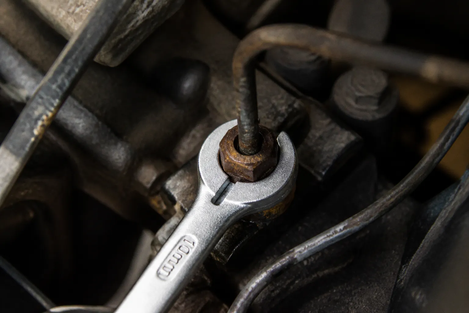
It determines whether torque is transferred into the fitting or into two narrow edges that deform under load.
Brake, fuel, and hydraulic line fittings are frequent failure points because the tubing prevents access from the side. The fitting is commonly made from brass or aluminum. Both materials are softer than tool steel. If the wrench is loose, incorrectly sized, or loaded at an angle, the hex can be rounded before the line is removed.
The correct tool is not selected because the fitting looks small. It is selected because the fitting is soft, partially inaccessible, and required to transmit torque around a tube.
The mechanics of torque: why open-end wrenches fail on lines
Torque is applied force multiplied by lever arm. The equation is simple. The contact pattern is not.
An open-end wrench transfers force through two opposing surfaces. The load is concentrated at the corners and outer edges of the fitting. If the wrench fits perfectly and remains perpendicular to the hex, the arrangement can work. If the wrench is one size too large, the load becomes worse. If the wrench is placed at an angle, contact reduces further.
The fitting then behaves as a small deformable component rather than a rigid hexagonal block.
A line fitting is not equivalent to a suspension fastener. It is smaller. It is commonly thinner. It may have been exposed to water, salt, heat, brake fluid, fuel residue, or galvanic corrosion. Corrosion increases the breakaway torque while reducing the usable strength of the hex. The tool must therefore distribute force over the remaining flats.
A flare nut wrench surrounds five sides of the fitting. Its head remains open through a slot, but the slot is narrow enough to retain the tubing while the wrench is seated. The applied load is distributed around more of the hexagonal profile.
The decisive difference is not wrench width. It is the number of fitting surfaces carrying the torque.
Flare nut wrench versus open end
The distinction can be reduced to contact geometry.
| Parameter | Open-end wrench | Flare nut wrench |
|---|---|---|
| Contact surfaces | Two flats | Five of six flats |
| Tube access | Open side entry | Slotted head passes over rigid tubing |
| Load concentration | High at two edges | Distributed across most of the hex |
| Suitability for soft fittings | Limited | Designed for line fittings |
| Typical use | General nuts and bolts | Brake, fuel, and hydraulic lines |
| Primary failure risk | Corner deformation and rounding | Slot spreading if overloaded or poorly fitted |
A standard six-point socket would surround the fitting more completely than either wrench. It cannot be installed when the rigid line exits through the fitting. That is the physical reason a socket is unavailable in many line-repair situations. The tube occupies the path through which the socket would need to pass.
An open-end wrench solves the access problem but sacrifices contact area. A flare nut wrench retains the slot and restores most of the surrounding support.
This is why the tool is also called a line wrench. The name describes the application, not a different operating principle.
Anatomy of the flare nut wrench: the five-sided advantage
The head contains a box-style opening with one section removed. The remaining steel forms a nearly enclosed hexagonal profile. The opening is aligned with the line. The tool is slid over the tubing and pushed onto the fitting.
The head must be fully seated. Partial engagement changes the load path. The wrench may still feel stable by hand, but the unsupported corner can become the point of failure as soon as torque increases.
The following sequence is the correct mechanical logic:
1. Identify the fitting size.
The wrench must match the hex across its flats. A near-size metric or SAE tool is not an acceptable substitute. The difference can be small enough to escape visual detection and large enough to damage the fitting.
2. Clear the line path.
The tool must pass over the rigid tube without being forced sideways. Bending the line to install the wrench places lateral load into the fitting and can crack or distort the tube.
3. Seat the head completely.
The wrench should contact the maximum available portion of the hex. The slot must be aligned with the tube. No visible gap should exist between the wrench head and the fitting flats.
4. Keep the handle in the plane of the fitting.
A straight pull is preferred. Side loading reduces contact and can make the wrench climb out of the hex.
5. Apply controlled breakaway force.
If the fitting does not move, more force is not automatically the correct next step. Penetrant, heat restrictions, component replacement strategy, and access must be evaluated before load is increased.
6. Stop when deformation begins.
Shiny displaced metal at the fitting corners indicates movement of the hex, not progress. Further torque after that point reduces the probability of removal without replacement.
The tool should be placed on the fitting before force is applied. It should not be hammered onto a damaged hex unless the replacement plan already includes the line or fitting. A flare nut wrench is designed to prevent damage to an intact fitting. It is not a recovery device for every rounded one.
Why the slot does not cancel the advantage
The open slot is the compromise. A closed box wrench would provide more complete circumferential support, but the tube would prevent installation. The flare nut wrench removes only the material required for tube access.
That opening creates a weak direction. It does not make the tool equivalent to an open-end wrench. Five contact surfaces remain available when the head is correctly fitted. Under excessive torque, however, the thinner walls around the slot can flex or spread. The tool is stronger in the intended application than an open-end wrench, but it is not immune to overload.
The distinction matters during seized fitting removal. A line wrench should be used to preserve a fitting that still has usable flats. It should not be treated as a substitute for a fully enclosed socket on heavy chassis hardware.
Material vulnerability: protecting brass and aluminum fittings
The fitting material changes the correct tool choice.
Brass and aluminum are used in line systems because they can be formed, sealed, and integrated with tubing without the same corrosion behavior as some steel components. Their lower hardness also creates the risk. The tool may remain visually intact while the fitting yields.
A standard open-end wrench can leave two narrow impressions in the fitting. Once those corners deform, the wrench develops additional clearance. Additional clearance produces more movement at the next pull. The process becomes self-reinforcing:
1. The wrench contacts only two flats.
2. The soft fitting yields at the loaded corners.
3. Clearance increases between wrench and hex.
4. The wrench slips or climbs.
5. The next load is concentrated on a smaller area.
6. The hex rounds further.
Pliers are worse for this task. Their jaws are not profiled for a flare nut. They apply force at arbitrary points and usually provide insufficient control over the fitting axis. Locking pliers may remove a severely damaged component, but they are not a preventive tool for brake or fuel line service.
The flare nut wrench interrupts the failure sequence at the second step. More of the hex remains supported. The fitting is less likely to crush at two corners. Torque is transferred through five sides instead of being concentrated on two.
This is the practical answer to why use a line wrench. The tool protects the component that is expensive, difficult, or unsafe to replace. A rounded brake line fitting can convert a short service operation into line replacement, additional bleeding, and a larger risk of introducing leaks.
Improper tool selection, including open-end or incorrect metric/SAE wrenches, is associated with nearly 30% of brake line fitting damage during repairs. The exact outcome depends on corrosion, access, fitting material, tool fit, and applied torque. The number should not be interpreted as a universal failure rate for every workshop. It identifies the scale of a recurring error: tool selection is a direct contributor to line damage.
A fitting that has not moved is still serviceable. A fitting that has started to round has already changed the repair decision.
Standard sizing: navigating SAE and metric line requirements
Imported vehicles require metric discipline. Many European and Asian vehicles use metric line fittings, with 10 mm being a common size. Domestic applications commonly use 7/16-inch fittings. These are not interchangeable standards.
A 10 mm wrench measures 10 mm across its intended flats. A 7/16-inch wrench measures 0.4375 inch, equivalent to approximately 11.11 mm. The difference is substantial for a small fitting. A tool that appears close may sit on only part of the hex.
The reverse error also occurs. A metric wrench may be forced onto an SAE fitting because the nominal sizes look similar. This is unacceptable on a soft line fitting. A near match is not a match.
A useful workshop arrangement separates line-wrench sizes by standard:
- Metric set: required for many European and Asian imports. A 10 mm flare nut wrench should be available before brake or hydraulic line work begins.
- SAE set: required for domestic vehicles and some older components. A 7/16-inch wrench is a common line-fitting size.
- Dedicated storage: metric and SAE tools should not be mixed in a single undifferentiated drawer. Misidentification is more likely when the difference is judged by eye.
- Clean contact surfaces: dirt, corrosion flakes, and paint between the wrench and fitting increase clearance. The hex should be brushed clean before the tool is seated.
- Correct tool profile: a general open-end wrench should not be substituted because the line is difficult to access.
The size marking on the tool is not sufficient. The fitting itself must be measured or positively identified. On a corroded fitting, the original flats may no longer provide a reliable visual reference. The tubing diameter and thread standard can help identify the system, but they do not replace measurement of the wrenching hex.
Metric and SAE confusion on imported vehicles
The vehicle badge is not a complete specification. Imported vehicles can contain replacement components from another market. A previous repair may have installed a line, caliper, master-cylinder component, or union with a different standard. The fitting must be measured at the point of service.
The decision gate is direct:
- If a correctly sized metric flare nut wrench seats fully, use it.
- If it does not seat, do not force the nearest SAE size.
- If an SAE tool seats but the fitting belongs to a metric system, verify the dimensions before applying torque.
- If neither standard seats correctly, stop. The fitting may be damaged, contaminated, or a different size.
The cost of stopping is measured in minutes. The cost of rounding a brake fitting is measured in parts and additional operations.
Applying torque without damaging the line
Tool design does not remove the need for correct force application. A flare nut wrench can still fail if the fitting is seized or the handle is loaded incorrectly.
The wrench should be pulled in the direction that keeps the head pressed onto the hex. Pushing with an open hand is less controlled because a sudden release can send the hand into adjacent components. A short handle is preferable when access is limited and the fitting is delicate. A long handle increases available torque and therefore increases the damage potential if the fitting does not move.
The first movement should be controlled. The objective is not maximum torque. The objective is to determine whether the fitting is releasing, deforming, or transferring force into the line.
Three outcomes are possible:
The fitting releases
Continue with steady movement. The wrench should remain fully seated. If the fitting turns but the tube twists with it, stop. The tube must remain stationary relative to the fitting. Twisting indicates that the line is being damaged or that the union is seized to the tube.
The fitting remains fixed
Do not extend the handle automatically. Corrosion may have bonded the threads. The fitting may be under residual load. The line may be unsupported. Access may be forcing the wrench into a poor angle.
The correct next operation depends on the component. Penetrant can be applied where appropriate. Heat may be restricted near brake fluid, fuel, plastic modules, wiring, seals, and painted surfaces. If the line is already scheduled for replacement, cutting the tube and using a six-point socket on the removed fitting may be safer than increasing load through the open slot. That is a repair strategy, not a general substitute for the line wrench.
The fitting begins to round
Stop immediately. The failure has moved from a removal problem to a component recovery problem. More force through the same tool will not restore the original geometry.
The fitting should be inspected under direct light. If the hex is compromised, the required procedure may include line replacement, fitting replacement, or controlled use of a dedicated extraction tool. On a brake system, the final repair must include leak verification and correct bleeding. A fitting that merely appears tight is not evidence of a safe seal.
When flare nut wrenches flex under load
The slot is the tool’s access feature and its structural limitation. Thin walls near the opening can spread if torque becomes excessive. This is more likely when the fitting is seized, the tool is poorly fitted, or the wrench is loaded with a long extension.
The exact torque threshold varies by tool design, steel section, heat treatment, head thickness, and load direction. There is no universal value that can be assigned to every flare nut wrench. A nominal size does not define the strength of the head.
Several conditions increase the probability of flex:
- The wrench is not fully seated on the fitting.
- The fitting has already lost material at one or more corners.
- A metric tool is being used on an SAE fitting, or the reverse.
- The handle is angled away from the fitting plane.
- A pipe or cheater bar is used to increase leverage.
- The fitting is heavily corroded.
- The line is being forced sideways to accommodate the tool.
- The wrench has a thin head or visible slot deformation.
- The tool is being used on a fastener outside its intended line-service application.
A flexing head changes contact during the pull. The wrench may initially engage five sides, then lose one or more surfaces as the slot opens. At that point, the load path approaches that of an open-end wrench, but with stored elastic energy in the tool.
The tool should be removed and inspected if spreading is visible. A flare nut wrench with a distorted slot should not be returned to service for precision line work. The fitting should also be checked for corner displacement, cracks, and thread damage.
Flare nut wrench versus six-point socket
The comparison is not a question of which tool is stronger in every situation. It is a question of access.
| Application | Preferred tool | Reason |
|---|---|---|
| Brake fitting with rigid tube attached | Flare nut wrench | The slotted head passes over the tube |
| Removed line fitting on a workbench | Six-point socket | Full enclosure is available |
| General suspension bolt | Six-point socket or box wrench | Line-wrench access feature is unnecessary |
| Damaged fitting scheduled for replacement | Extraction tool or socket strategy | Preservation is no longer the primary objective |
| Fuel or hydraulic line fitting | Correctly sized flare nut wrench | Soft fitting and restricted access require distributed contact |
A line wrench should not replace standard sockets for general heavy-duty chassis bolts. Its geometry is optimized for line fittings. Its strength and access profile are different from those of a closed socket.
A controlled procedure for brake and hydraulic line fittings
The following procedure is deliberately conservative. The fitting is treated as a precision sealing component.
1. Stabilize the vehicle and expose the fitting.
Vehicle support must be secure. The line should be visible enough to identify the fitting, tube direction, and adjacent components.
2. Clean the hex and surrounding threads.
Dirt and corrosion should be removed without forcing debris into an open hydraulic system. The tool-contact surfaces must be visible.
3. Measure the fitting.
Confirm metric or SAE size. On an import vehicle, metric sizing should be checked first, not assumed.
4. Select the flare nut wrench.
The head must pass over the tube without contact that distorts the line. The wrench must sit squarely on the hex.
5. Support the opposing component.
If a union or hose connection is being separated, the stationary side may require a second wrench. The line must not be twisted while the fitting is turned.
6. Apply controlled torque.
Use the shortest suitable handle. Maintain alignment. Observe the fitting, tube, and tool head during the first movement.
7. Classify the result.
Release, no movement, tube twist, tool flex, and hex deformation are different conditions. They require different next actions.
8. Inspect after separation.
Threads, flare surfaces, tube ends, and the wrench head must be checked. A fitting that came loose can still be damaged enough to leak after reassembly.
9. Reassemble to the vehicle manufacturer’s specification.
Thread engagement, flare condition, line routing, and support points must be correct. The fitting should not be tightened by feel alone when a specified torque is available.
10. Verify the completed system.
Brake or hydraulic systems require leak inspection and functional testing. The final condition is not established by the absence of visible fluid during the first inspection.
The exact baseline for a successful repair
The repair is verified only when the hardware returns to defined conditions.
The required baseline is:
- The flare nut wrench size matches the fitting across its flats.
- The tool contacted five of the six available sides during removal.
- The wrench head did not spread or deform.
- The fitting hex remains usable, with no new rounding or crushed corners.
- The rigid tube was not twisted, kinked, or forced sideways.
- The flare or sealing surface is free from visible damage.
- The line remains correctly routed and supported.
- The connection is tightened to the specified vehicle value.
- No fluid leakage is present after system pressurization.
- Brake pedal or hydraulic-system operation is stable after service.
- The fitting remains dry during a second inspection after operation.
That is the practical flare nut wrench design difference. The tool does not create more torque. It controls where torque enters the fitting. Two contact surfaces concentrate force. Five contact surfaces distribute it. On soft brass or aluminum line fittings, that geometry determines whether the component survives the first removal attempt.
A correctly sized line wrench is therefore not a specialty accessory added after the repair begins. It is the baseline tool for the repair to remain a repair rather than become a line-replacement operation.